Compressor and oil-cooling system

a compressor and oil cooling technology, applied in the field of compressors, can solve the problems of increasing the potential for inaccuracy in the alignment of components, more expensive or time-consuming manufacturing, etc., and achieve the effects of reducing suction-gas superheat, improving compressor volumetric efficiency, and improving performan

Active Publication Date: 2010-12-09
COPELAND LP
View PDF20 Cites 43 Cited by
  • Summary
  • Abstract
  • Description
  • Claims
  • Application Information

AI Technical Summary

Benefits of technology

[0006]A lubricant (e.g., oil) sump can be employed in the shell of the compressor to store the lubricant charge. The sump can be placed in either the low-pressure zone or the high-pressure zone. The lubricant serves to lubricate the moving components of the compressor and can flow with the working fluid through the scroll assemblies and be discharged along with the working fluid into the discharge-pressure zone of the compressor. The temperature of the lubricant being discharged, along with that of the working fluid, is elevated. Cooling the lubricant prior to flowing back through the compressor and lubricating the components therein can reduce suction-gas superheat, thereby improving compressor volumetric efficiency and providing better performance. The reduced lubricant temperature may also improve compressor reliability by cooling the suction gas and the motor. Cooling the lubricant can also keep the viscosity of the lubricant at a desirable level for maintaining oil film thickness between moving parts.
[0007]Within the compressor, the lubricant is provided to the various moving components. Improving the distribution of the lubricant throughout the compressor can advantageously improve the performance and / or longevity of the compressor.
[0008]Within the compressor, the proper alignment of the various components relative to one another can improve the performance of the compressor and / or reduce the sound generated by the compressor. Improving the alignment between the various components, such as the non-orbiting scroll member, the bearings, and the motor, can improve the performance and / or reduce the sound generated by the compressor. The compressors typically use numerous discrete components that are assembled together within the shell to provide the alignment. The use of these numerous separate and discrete components, however, increases the potential for inaccuracy in the alignment of the components and, further, can be more expensive or time consuming to manufacture as tighter tolerances for the various components are required to produce the desired alignment.

Problems solved by technology

The use of these numerous separate and discrete components, however, increases the potential for inaccuracy in the alignment of the components and, further, can be more expensive or time consuming to manufacture as tighter tolerances for the various components are required to produce the desired alignment.

Method used


Image

  • Compressor and oil-cooling system
  • Compressor and oil-cooling system
  • Compressor and oil-cooling system

Examples


Embodiment Construction

[0033]The following description is merely exemplary in nature and is in no way intended to limit the present disclosure, its application, or uses.

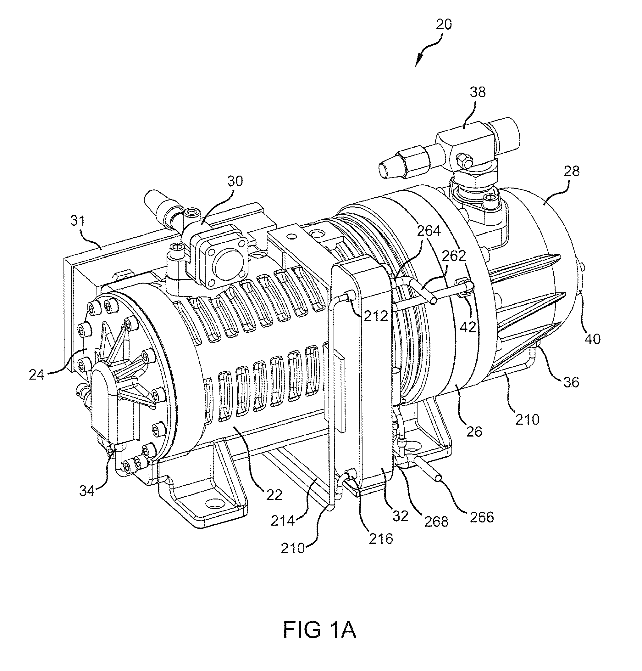
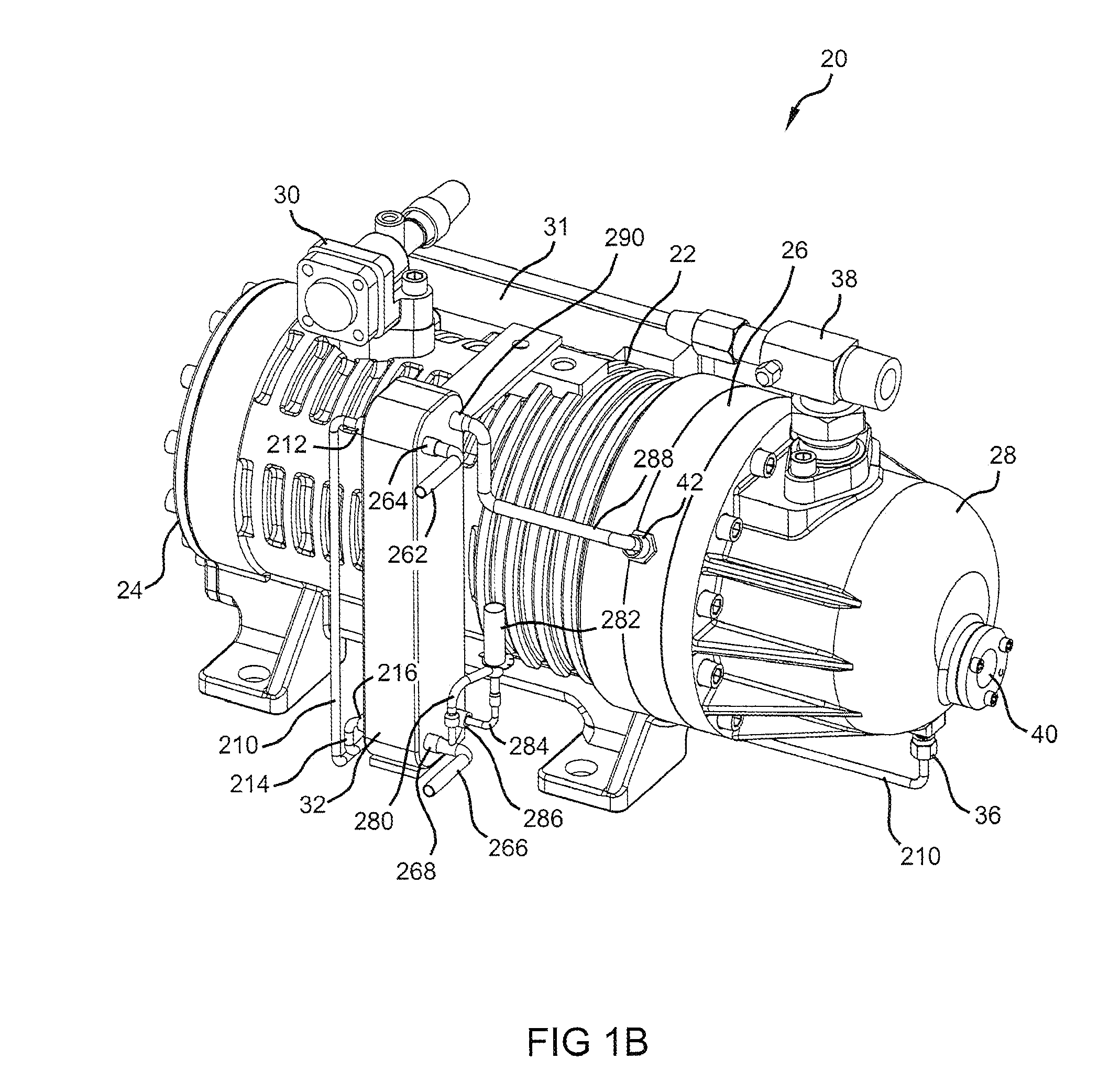
[0034]Referring to FIGS. 1-3 and 10, a compressor 20 according to the present teachings is shown. Compressor 20 is a semi-hermetic compressor having a housing or shell 22 with opposite ends 23, 25. A low-side (LS) end cap 24 is attached to end 23 and a partition member 26 and a high-side (HS) end cap 28 are attached to end 25. LS end cap 24, partition 26, and HS end cap 28 can be attached to shell 22 with bolts or other types of fasteners, as known in the art. Other major elements affixed to shell 22 can include a working fluid inlet fitting 30, a heat exchanger 32, and an electronics box 31 that can communicate with sensors and other components within or outside compressor 20. LS end cap 24 includes a lubricant inlet fitting 34. HS end cap 28 may define a high-side lubricant sump and includes a lubricant outlet fitting 36. HS end cap 28 c...


PUM


Abstract

An external heat exchanger is used to transfer heat from a compressor lubricant to an expanded working fluid, thereby cooling the lubricant. The heat exchanger may also be used to sub-cool condensed working fluid with the same flow of expanded working fluid. A horizontal scroll-type compressor includes an intermediate lubricant sump between a main bearing support and a scroll member. A counterweight on the crankshaft can travel through the lubricant in the intermediate sump to splash the lubricant around. A horizontal scroll-type compressor can include multiple machined surfaces that are utilized to precisely center and align components of the compressor.

Description

CROSS-REFERENCE TO RELATED APPLICATIONS[0001]This application claims the benefit of U.S. Provisional Application No. 61 / 178,720, filed on May 15, 2009. The entire disclosure of the above application is incorporated herein by reference.FIELD OF THE INVENTION[0002]The present invention relates generally to compressor machines. More particularly, the present invention relates to a compressor and an oil-cooling system that cools the lubricating oil that flows through the compressor.BACKGROUND AND SUMMARY OF THE INVENTION[0003]Compressor machines in general, and particularly scroll compressors, are often disposed in a hermetic or semi-hermetic shell which defines a chamber within which is disposed a working fluid. A partition within the shell often divides the chamber into a discharge-pressure zone and a suction-pressure zone. In a low-side arrangement, a scroll assembly is located within the suction-pressure zone for compressing the working fluid. Generally, these scroll assemblies inco...

Claims


Application Information

Patent Timeline
Patent Type & Authority Applications(United States)
IPC IPC(8): F04C29/02F25B31/00F04C29/04
CPCF04C18/0253F04C23/008F04C29/028F04C2230/603F04C29/021F04C2270/19F25B31/004F25B2400/13F04C18/0207F04C2240/81
Inventor GUO, WEIHUAZHAN, HONGHONGWANG, SHIGUO, HUAMINGWANG, GUIBINZHANG, JIN
Owner COPELAND LP
Why Eureka
Try Eureka