A heat pump system
A heat pump system and heat exchanger technology, applied in the field of thermal management, can solve the problems of increasing compressor suction superheat and reducing heat pump performance, and achieve the effect of reducing suction superheat and improving performance
- Summary
- Abstract
- Description
- Claims
- Application Information
AI Technical Summary
Problems solved by technology
Method used
Image
Examples
Embodiment 1
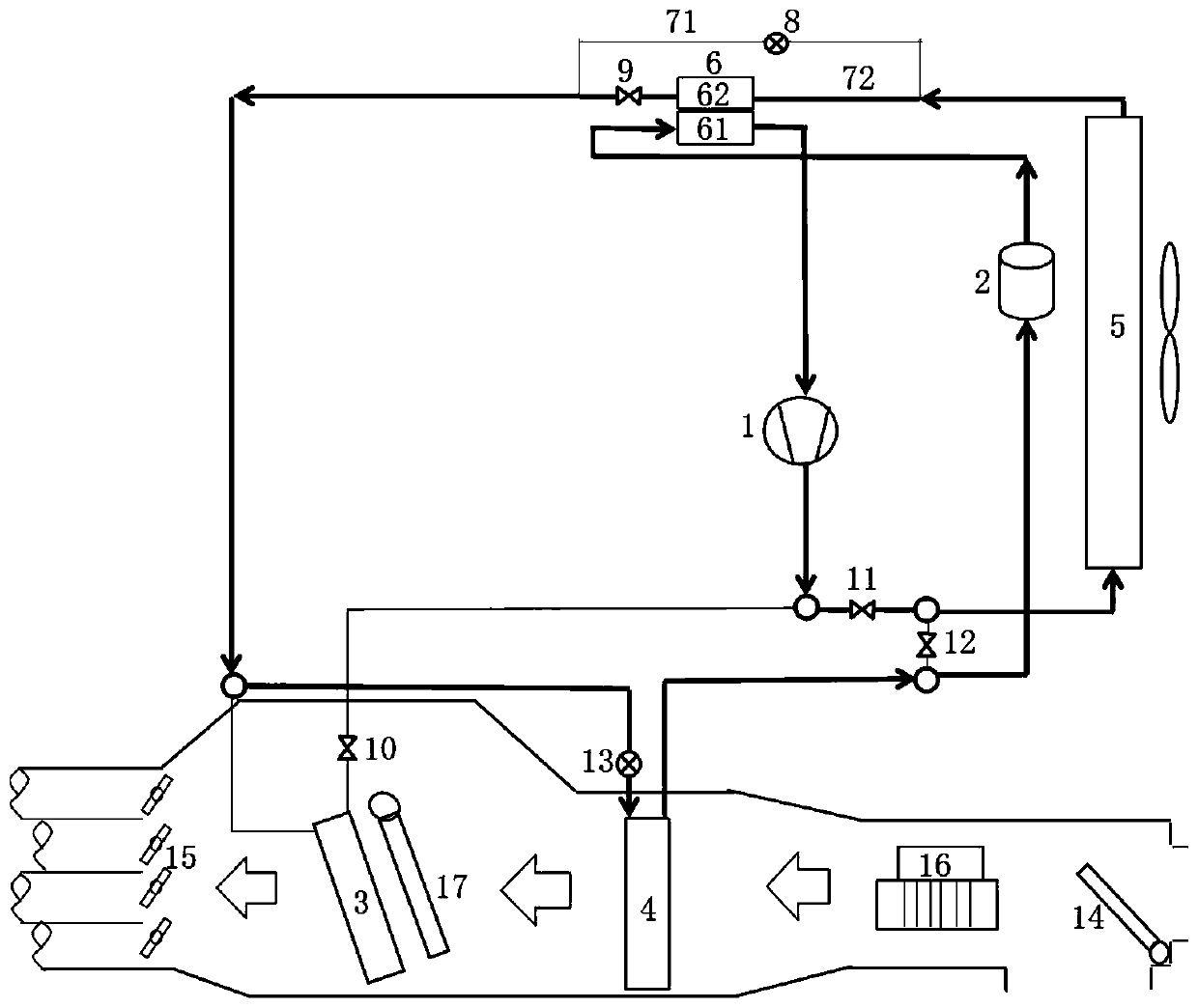
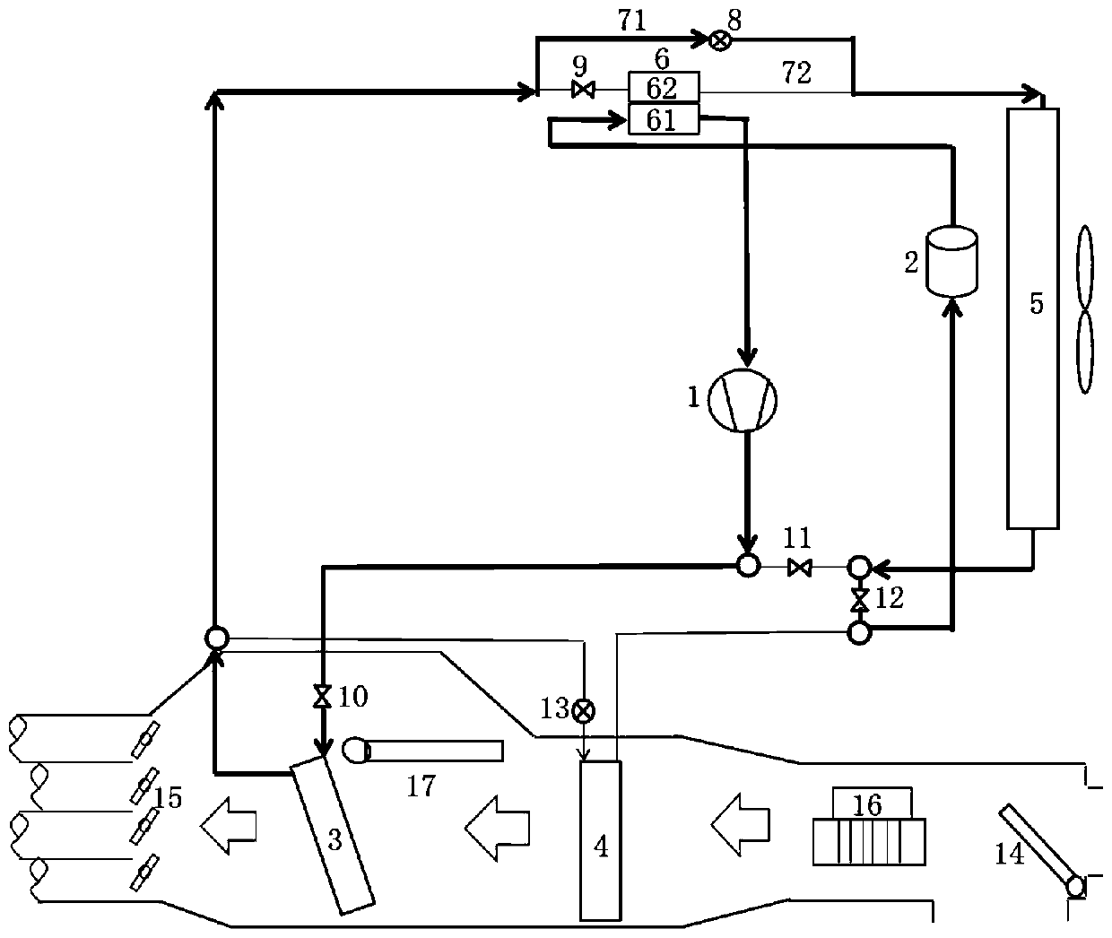
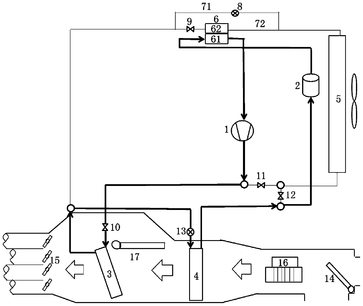
[0027] like Figure 1-Figure 5 As shown, this embodiment provides a heat pump system, which has multiple working modes such as cooling mode, heating mode and dehumidification mode (or demisting mode). Specifically, the heat pump system includes an air conditioning box for adjusting the temperature and / or humidity in the compartment, and the heat pump system also includes a compressor 1, a gas-liquid separator 2, a third heat exchanger 5 and an intermediate heat exchanger 6; An air duct is arranged inside the box, and one end of the air duct is provided with a first damper 14 for introducing circulating air into the air duct, and the other end of the air duct is provided with a grille 15 for supplying air to the compartment. The fan 16, the second heat exchanger 4 and the first heat exchanger 3 are arranged in sequence from the inlet to the outlet, wherein the first heat exchanger 3 is provided with a second damper 17 for controlling the flow through the first heat exchanger 3....
Embodiment 2
[0041] like Figure 5 As shown, this embodiment provides yet another heat pump system, which is basically the same in structure and working principle as the air-conditioning system in Embodiment 1, the difference lies in: the first heat exchanger 3 and / or the second heat exchanger in this embodiment Device 4 is not arranged in the air duct. Specifically, the first heat exchanger 3 in this embodiment may include a refrigerant flow channel and a cooling liquid flow channel, and the refrigerant flow channel of the first heat exchanger 3 and the cooling liquid flow channel of the first heat exchanger 3 are relatively disconnected. , the refrigerant in the refrigerant flow path of the first heat exchanger 3 and the coolant in the coolant flow path of the first heat exchanger 3 can perform heat exchange; further, the heat pump system also includes a fourth heat exchanger 19 and a fourth heat exchanger 19 A pump 20 , the cooling liquid channel of the first heat exchanger 3 communica...
Embodiment 3
[0043] like Figure 6-Figure 11 As shown, this embodiment provides yet another heat pump system, which is basically the same in structure and working principle as the air conditioning system in Embodiment 1, the difference is that the second valve 10 and the third valve 11 are not provided in this embodiment And the fourth valve member 12, but set the first fluid switching valve 18, such as Figure 10 and Figure 11 As shown, the first fluid switching valve 18 has four ports, which are respectively the first port 181 of the first fluid switching valve, the second port 182 of the first fluid switching valve, the third port 183 of the first fluid switching valve and The fourth port 184 of the first fluid switching valve. The first fluid switching valve 18 includes a first working mode and a second working mode, such as Figure 10 As shown, in the first working mode of the first fluid switching valve 18, the third port 183 of the first fluid switching valve communicates with t...
PUM
 Abstract
Description
Claims
Application Information
 - R&D
- Intellectual Property
- Life Sciences
- Materials
- Tech Scout
- Unparalleled Data Quality
- Higher Quality Content
- 60% Fewer Hallucinations
Browse by: Latest US Patents, China's latest patents, Technical Efficacy Thesaurus, Application Domain, Technology Topic, Popular Technical Reports.
© 2025 PatSnap. All rights reserved.Legal|Privacy policy|Modern Slavery Act Transparency Statement|Sitemap|About US| Contact US: help@patsnap.com


