Wig and its manufacturing method

a manufacturing method and technology for wigs, applied in the field of wigs, can solve the problems of wig hair coming off, hair erection, hair hammering, etc., and achieve the effects of preventing knot loosening, minimizing the load on the implanted hair, and facilitating erection of hair

Inactive Publication Date: 2010-12-09
UNIHAIR COMPANY LIMITED
View PDF19 Cites 3 Cited by
  • Summary
  • Abstract
  • Description
  • Claims
  • Application Information

AI Technical Summary

Benefits of technology

[0024]According to the wig of the present invention, since the relatively large knots are placed on the back of the wig base, the knots are invisible through the gap between the hairs planted from the surface of the wig base, making the wig hardly recognizable as a wig. In addition, smooth brushing is allowed even when the wig is worn because the teeth of a brush do not catch the knots, thus minimizing the load on the hair implanted. Damage on the hair or loosening of the knots and resulting coming off of hair can thus be prevented. Furthermore, since the knots are placed on the back of the wig base, the teeth of a brush do not contact the knots directly when brushing or washing is performed. Loosening of the knots can thus be prevented. In addition, since adhesion of the hair to the wig base is so strong that no adhesive is required to fasten the hair after implantation. Since only one wig

Problems solved by technology

In addition, when hair is brushed, the teeth of a brush may catch these knots, hampering smooth brushing.
If brushing is given repeatedly, the knots may become loose, thus res

Method used


Image

  • Wig and its manufacturing method
  • Wig and its manufacturing method
  • Wig and its manufacturing method

Examples


example 1

Example 1

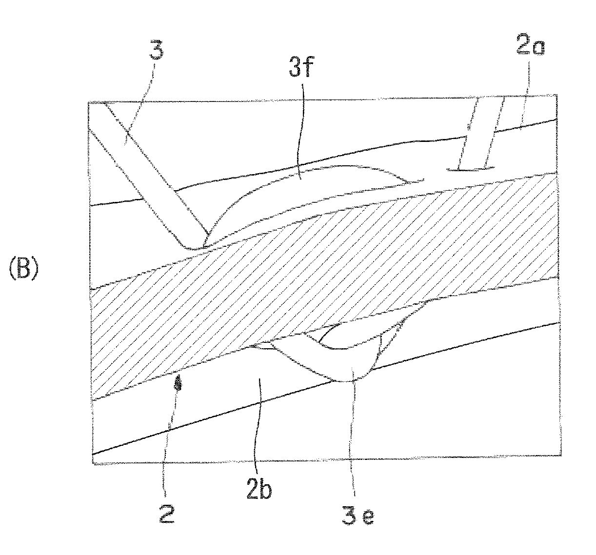
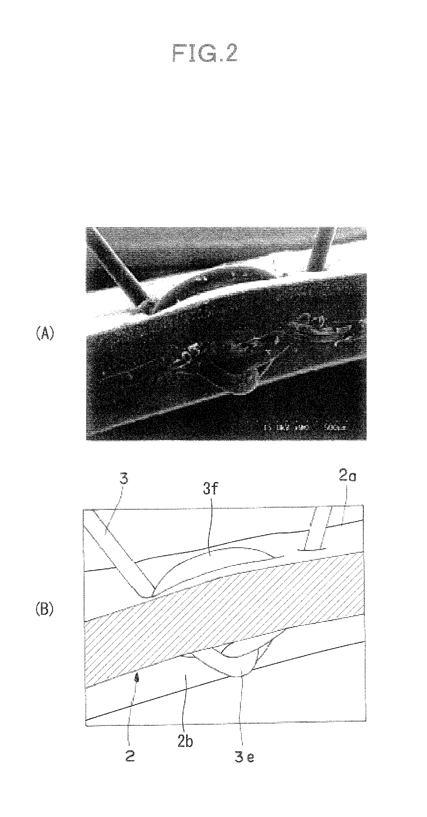
[0060]As example 1, a wig was produced by the method in the form of implementation described above. Soft 0.20 mm-thick artificial skin made of a polyurethane resin was used as a wig base, and a number of 0.08 mm-thick artificial hairs made of a polyamide resin were implanted. FIG. 2, FIG. 3, and FIG. 4 are cross-sectional views showing the implanted hair of the wig, viewed at an oblique angle from above, at an oblique angle from underneath, and from the bottom respectively. (A) of FIG. 2, FIG. 3, and FIG. 4 is a scanning electron microscopic image taken at 90-, 80-, and 80-fold magnification respectively. (B) is a figure for describing the members. It is apparent from these figures that the knot 3e of the wig of the example is on the back 2b of the wig base 2, and the bridging portion 3f linked to the knot 3e is on the surface 2a.


PUM


Abstract

By undergoing a first step for passing a hook portion 1a of a hair-implanting needle 1 from the surface 2a to the back 2b of a wig base 2 and passing the hook portion back onto the surface at another position, a second step for catching a loop 3b formed at the turning position of hair 3 folded, a third step for pulling the loop 3b out of the wig base 2 in a state wherein the hair is caught by the hair-implanting needle 1, a fourth step for catching one side3a of the hair with the hook portion 1a, a fifth step for pulling the hair-implanting needle out of the loop 3b in this state, a sixth step for forming a knot by pulling one side 3a of the hair while holding the other side 3b, and a seventh step for moving the knot 3e to the back 2b of the wig base by pulling the other side 3b of the hair while holding the one side 3a of the hair, a wig wherein the knot 3e of the hair 3 is on the back 2b of the wig base is produced.

Description

TECHNICAL FIELD[0001]The present invention relates to a wig worn on a head and a method for manufacturing the wig, more specifically the wig wherein the part that ties hair to a wig base is not placed on the surface of the wig base and has sufficient adhesion, and the manufacturing method of the wig.BACKGROUND ART[0002]Conventionally, a wig is manufactured by implanting human or artificial hair to a wig base in a shape of a head made of artificial synthetic resin skin or a net material, and by applying a hair adhesive, as required, to the back of the wig base on which the hair has been planted. As disclosed in patent literature 1, planting methods such as single planting, half-knot planting, and split-knot planting are known.[0003]All of the planting methods disclosed in patent literature 1 make pairs of holes on a wig base using a hook, etc., make hair pass through these holes, and tie them on the surface of the wig base, meaning that the knots are placed on the surface of the wig ...

Claims


Application Information

Patent Timeline
IPC IPC(8): A41G3/00
CPCA41G3/0075A41G3/0066
Inventor KUROYANAGI, MAKIKOIMAI, SAKIKO
Owner UNIHAIR COMPANY LIMITED
Why Eureka
Try Eureka