Water supply apparatus

a technology of water supply apparatus and water supply tube, which is applied in the direction of process and machine control, positive displacement liquid engine, instruments, etc., can solve the problems of decrease in the lifetime of various sensors, and failure of the control substrate, so as to achieve a higher level of resistance to external causes, operate reliably, and avoid surge and noise.

Active Publication Date: 2010-12-09
EBARA CORP
View PDF15 Cites 7 Cited by
  • Summary
  • Abstract
  • Description
  • Claims
  • Application Information

AI Technical Summary

Benefits of technology

[0078](2) Because one control substrate is connected to the plurality of inverters in series by the communication lines and the other control substrate is connected to the plurality of inverters in series by the different communication lines, even if an abnormality occurs in one of the multiple sets of communication lines, the communication can be maintained by the other set of communication lines. Therefore, the inverters can be prevented from going out of control that can be caused by a failure of the communication lines due to noise or the like.
[0079](3) Because the systems, connected to the backup control substrate, have a higher level of tolerance to the surge and noise and a higher level of r

Problems solved by technology

However, the control substrate is susceptible to surge and noise caused by lightning, which often cause a failure of the control substrate.
Further, decrease in lifetime of various sensors due to consumption thereof may often cause malfunction of the control substrate.
Consequently, when one control substrate fails and another control substrate in a standby state is to be started, the backup operation may not be performed due to malfunction of the control substrate.
In this manner, although the water supply apparatus has the backup function, such function may not work.
Abnormalities tha

Method used


Image

  • Water supply apparatus
  • Water supply apparatus
  • Water supply apparatus

Examples


Embodiment Construction

[0100]A water supply apparatus according to embodiments of the present invention will be described below with reference to FIG. 1 through FIG. 17. In FIG. 1 through FIG. 17, the same or corresponding structural elements are denoted by the same reference numerals and repetitive explanations are omitted.

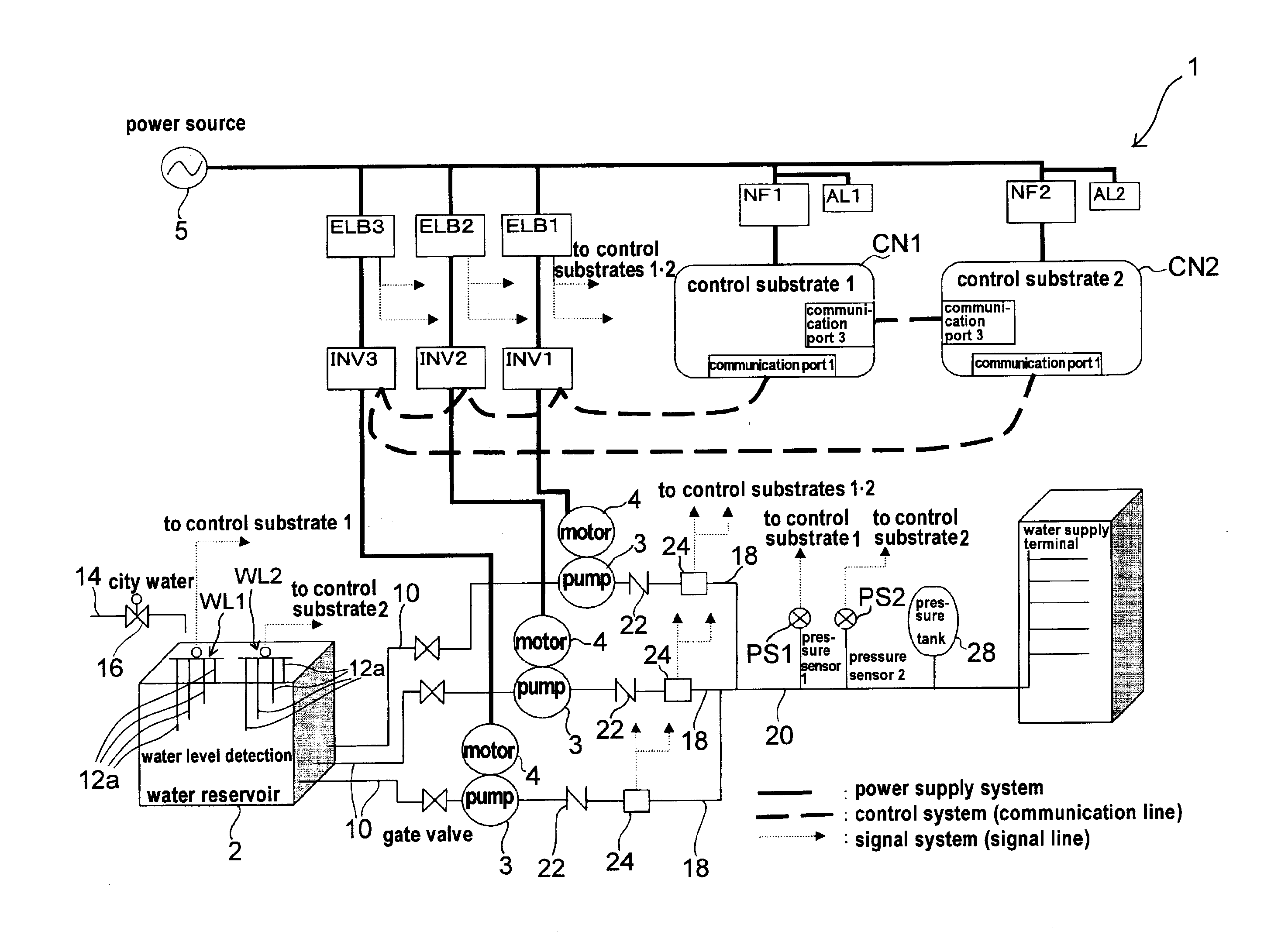
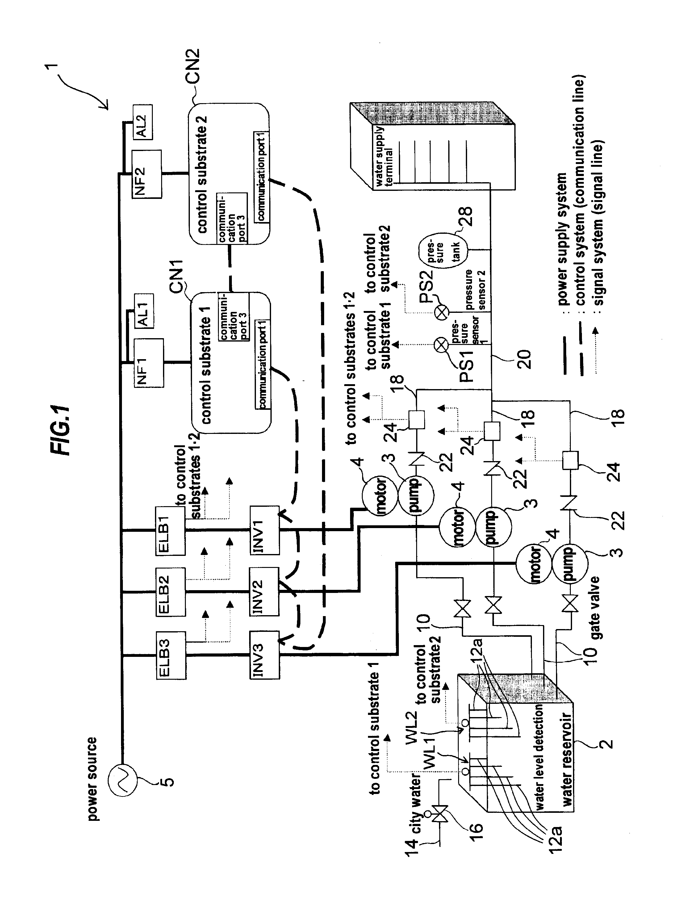
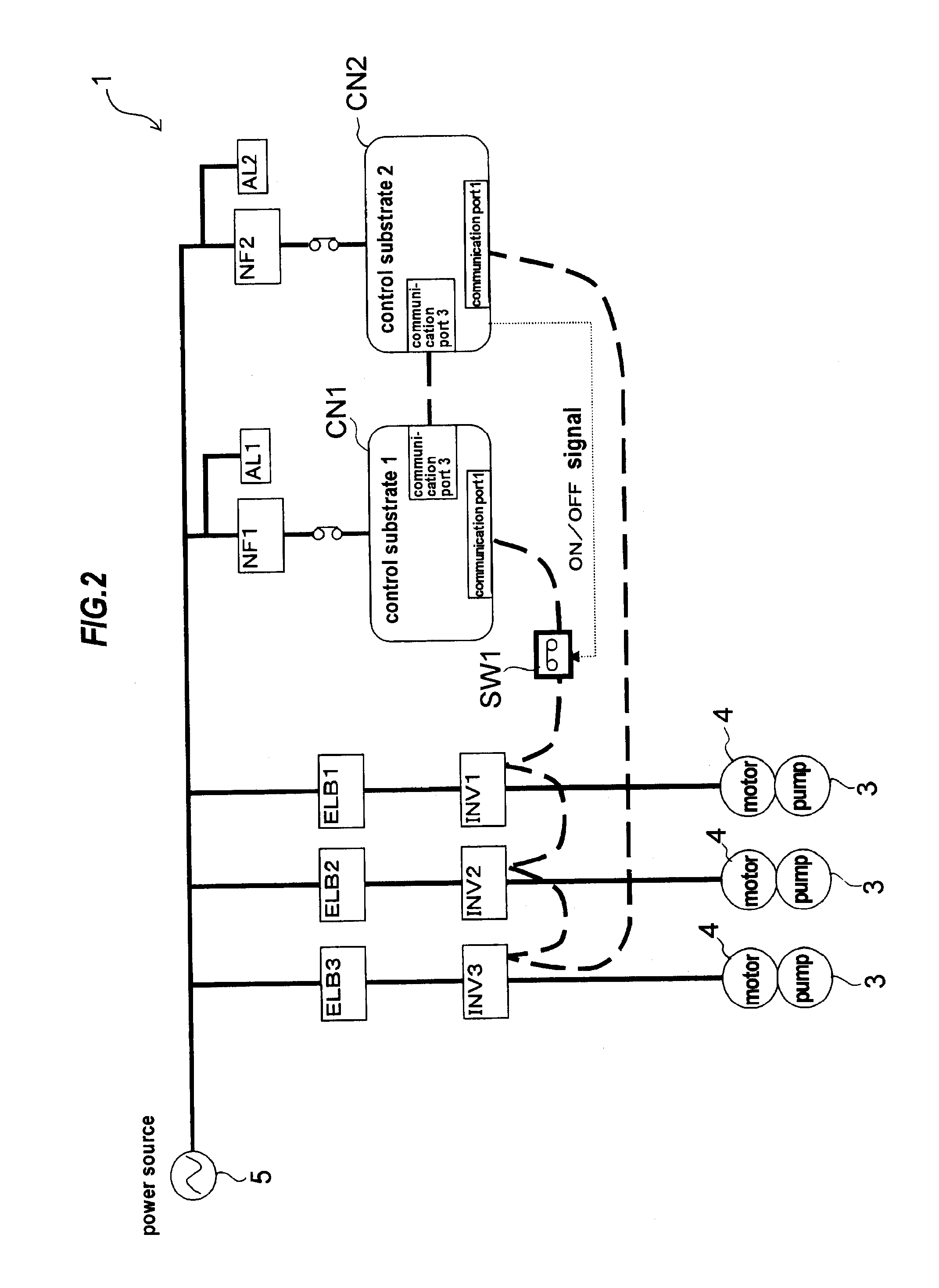
[0101]FIG. 1 is a schematic view showing an entire structure of a water supply apparatus 1 according to the present invention. In FIG. 1, solid lines (thick lines) represent a power supply system, dashed lines represent a control system (communication lines), and arrows represent a signal system (signal lines). The water supply apparatus includes a plurality of pumps and a plurality of inverters. In the present embodiment, the water supply apparatus, having three pumps and three inverters, will be described.

[0102]As shown in FIG. 1, the water supply apparatus 1 includes a water reservoir 2, three pumps 3 coupled to the water reservoir 2 via pipes 10, three motors 4 for driving the thre...


PUM


Abstract

The present invention provides a water supply apparatus capable of performing a backup operation, without lowering water supply capability, when a failure has occurred in one control substrate due to surge or noise caused by lightning or due to lifetimes of various sensors, by switching to the other control substrate, and capable of reliably performing the backup operation by means of devices that prevent failure of the control substrates. The water supply apparatus (1) includes: a plurality of pumps (3); a plurality of inverters (INV) each configured to change and control a rotational frequency of a corresponding one of the plurality of pumps (3); and a plurality of control substrates (CN) configured to control the plurality of inverters (INV). When an abnormality occurs in one control substrate, other control substrate backs up the one control substrate to thereby allow the water supply apparatus to continue its operations. The one control substrate, the plurality of inverters (INV), and the other control substrate are connected in series by communication lines. A switch (SW1) for turning on and off a communication is provided on the communication lines.

Description

TECHNICAL FIELD[0001]The present invention relates to a water supply apparatus, and more particularly to a water supply apparatus having multiple pumps and multiple inverters for supplying water to an apartment house or the like by operating the pumps at variable speeds.BACKGROUND ART[0002]A water supply apparatus, which is installed in an apartment house or a building, is a device for supplying water to respective terminal water outlets. In the water supply apparatus, it is a common technique to operate a pump at variable speeds by using an inverter that converts frequency and voltage of a commercial AC power supply to desired frequency and voltage. The inverter is capable of changing rotational speed of a motor, which drives the pump, as desired. Therefore, the pump can be operated at an optimal rotational speed corresponding to a load, and energy can be saved compared to a case of operating the pump at a rated speed.[0003]This type of water supply apparatus may have a plurality o...

Claims


Application Information

Patent Timeline
IPC IPC(8): E03B11/16
CPCF04D15/0066G05B9/03E03C1/025F04D15/029Y10T137/86163Y10T137/86131F04B41/06
Inventor KOMATSU, TAKAHIDEKANEDA, KAZUHIROTEJIMA, TOMOHARUHIGAKI, NOBUHIROMIYAUCHI, SACHIKO
Owner EBARA CORP
Why Eureka
Try Eureka