Laminating machine

a technology of laminating machine and workpiece, which is applied in the direction of lamination, mechanical working/deformation, chemistry apparatus and processes, etc., can solve the problems of workpieces whose dimensions are less than, workpieces end up creased, and get stuck in the laminating machine, damaging the precious paper document in the workpi

Inactive Publication Date: 2010-12-09
TEX YEAR INDS
View PDF5 Cites 7 Cited by
  • Summary
  • Abstract
  • Description
  • Claims
  • Application Information

AI Technical Summary

Benefits of technology

[0009]A primary objective of the present invention is to provide oppositely disposed upper and lower guide plates in a laminating machine such that a workpiece to be laminated passes through a guide slot formed between the upper and lower guide plates. Therein, the upper guide plate can be pushed upward, and a micro switch is provided above the upper guide plate for controlling the rotation of roller sets. If t

Problems solved by technology

However, such design rule may cause trouble to workpieces whose dimensions are less than the maximum design specifications.
More specifically, if a workpiece falling short of the maximum design width is fed into the lamination machine in such a way that the leading end of the workpiece turns to a side upon touching the first roller set, the entire workpiece may pass through between the following roller sets slantingly during the hot press process so that the workpiece ends up creased and gets stuck in the laminating machine, thereby damaging the precious paper document in the workpiece.
If the workpiece is jammed in the laminating machine for a long time, the films may overheat, deform, and eventual

Method used


Image

  • Laminating machine
  • Laminating machine
  • Laminating machine

Examples


Embodiment Construction

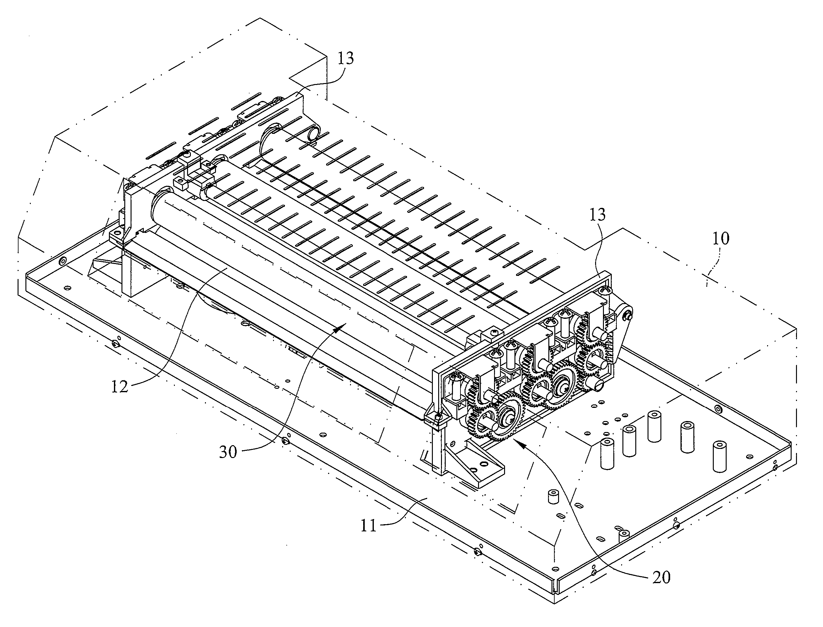
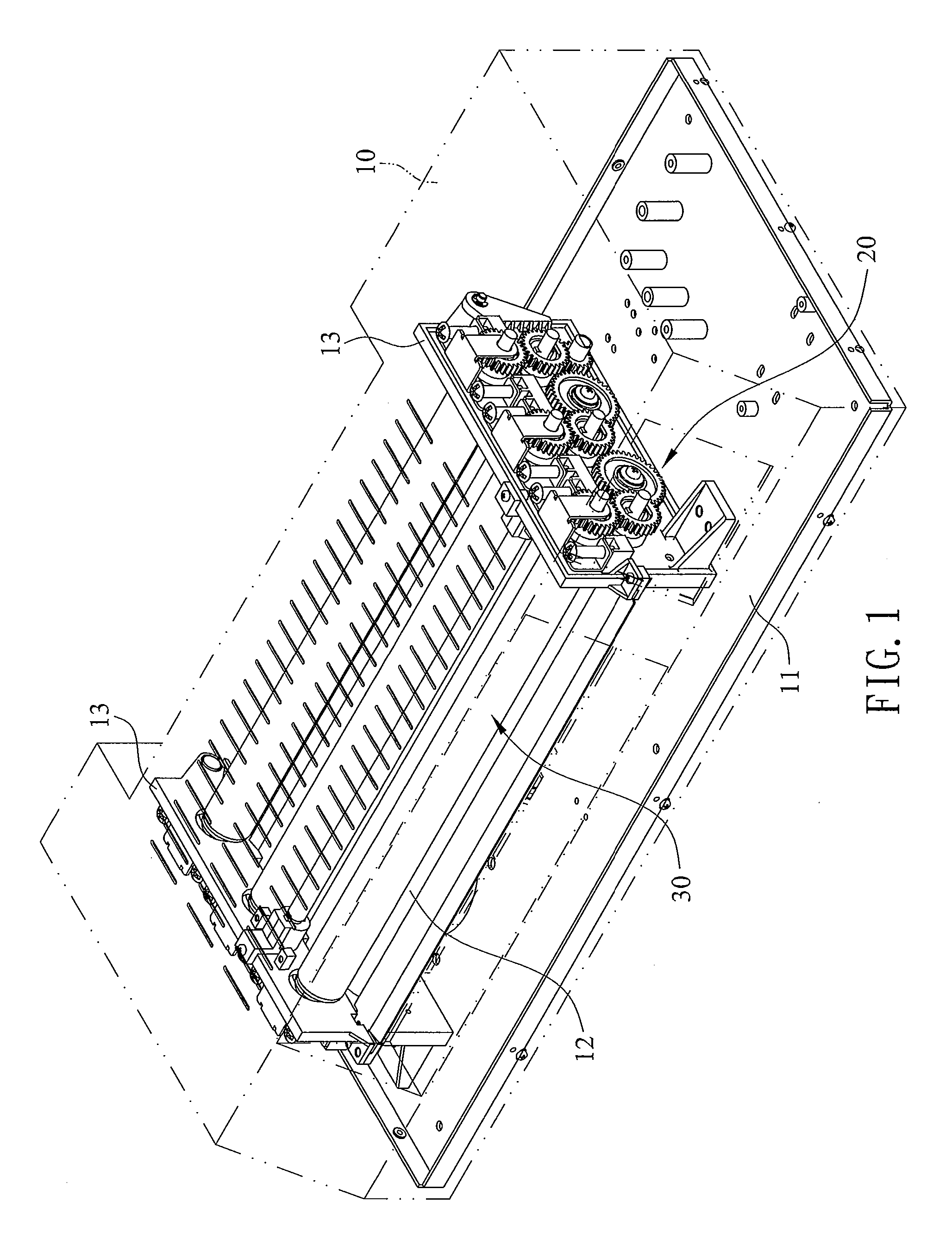
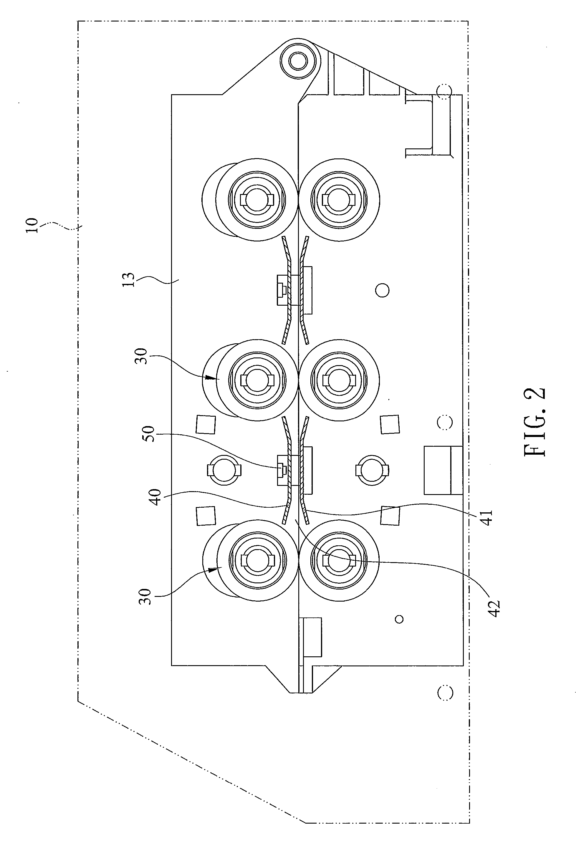
[0021]Referring to FIG. 1, a laminating machine according to the present invention includes a machine body 10 having a base 11. A pair of frames 13 are mounted on the base 11 and arranged opposite each other. Referring to FIG. 1 in conjunction with FIG. 3 and FIG. 5, each of the frames 13 is formed with a plurality of axial holes 131 such that roller sets 30 are pivotally provided between the corresponding axial holes 131 of the two frames 13. In addition, each of the frames 13 is formed with insertion notches 130 between the axial holes 131. The insertion notches 130 of one frame 13 correspond in position to the insertion holes 130 of the other frame 13. Furthermore, at least one of the insertion notches 130 is provided thereabove with a micro switch 50 configured for activating a reverse rotation mechanism of the roller sets 30. The circuit design of the micro switch 50 and the reverse rotation mechanism is not a technical feature of the present invention and therefore will not be...


PUM

PropertyMeasurementUnit
Thicknessaaaaaaaaaa
Shapeaaaaaaaaaa

Abstract

A laminating machine is provided therein with an upper guide plate and a lower guide plate that disposed opposite each other. A workpiece to be laminated passes through a guide slot formed between the upper and lower guide plates, wherein the upper guide plate can be pushed upward, and a micro switch is provided above the upper guide plate for controlling the rotation of roller sets. If the workpiece is too thick or is somehow impeded such that the workpiece creases, the upper guide plate will be pushed upward by the workpiece and therefore touches the micro switch. As a result, another circuit is activated to rotate the roller sets reversely and thereby eject the workpiece. Hence, not only is the laminating machine protected and saved from a lot of maintenance work, but also precious paper documents, such as photos, in the workpiece are well preserved.

Description

BACKGROUND OF THE INVENTION[0001]1. Technical Field[0002]The present invention relates to laminating machines and, more particularly, to a laminating machine having a safety device such that, when a workpiece fed into the laminating machine is impeded, a mechanism for rotating rollers of the laminating machine in a reverse direction is activated to eject the workpiece.[0003]2. Description of Related Art[0004]Lamination is the easiest and most common solution to preserving important paper documents, such as photos, which tend to yellow with age or are easily damaged. Basically, lamination is carried out in the following manner. A paper document is placed between two slightly larger films which are sealed together at one end and left open at the opposite end. Then, the films with the paper document sandwiched therebetween are fed into the feed port of a laminating machine, with the sealed end of the films as the leading end. After being heated and rolled by the laminating machine, the...

Claims


Application Information

Patent Timeline
IPC IPC(8): B32B37/10
CPCB32B37/0053B32B37/185Y10T156/1741B32B2037/0061B32B41/02
Inventor CHOU, KUANG-HUI
Owner TEX YEAR INDS
Why Eureka
Try Eureka