

Electric discharge machining device
- Summary
- Abstract
- Description
- Claims
- Application Information
AI Technical Summary
Benefits of technology
Problems solved by technology
Method used
Image

Examples
first embodiment
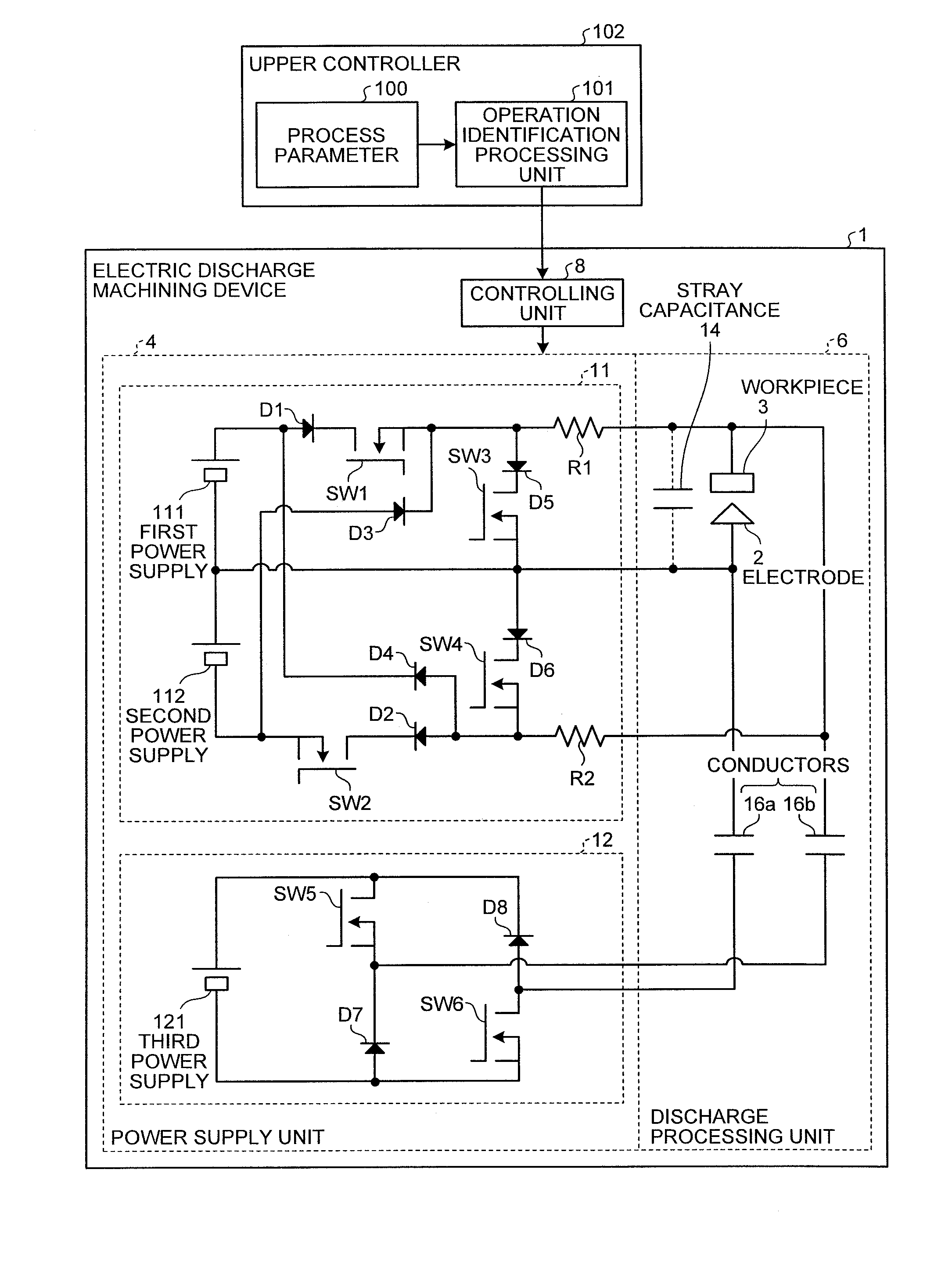
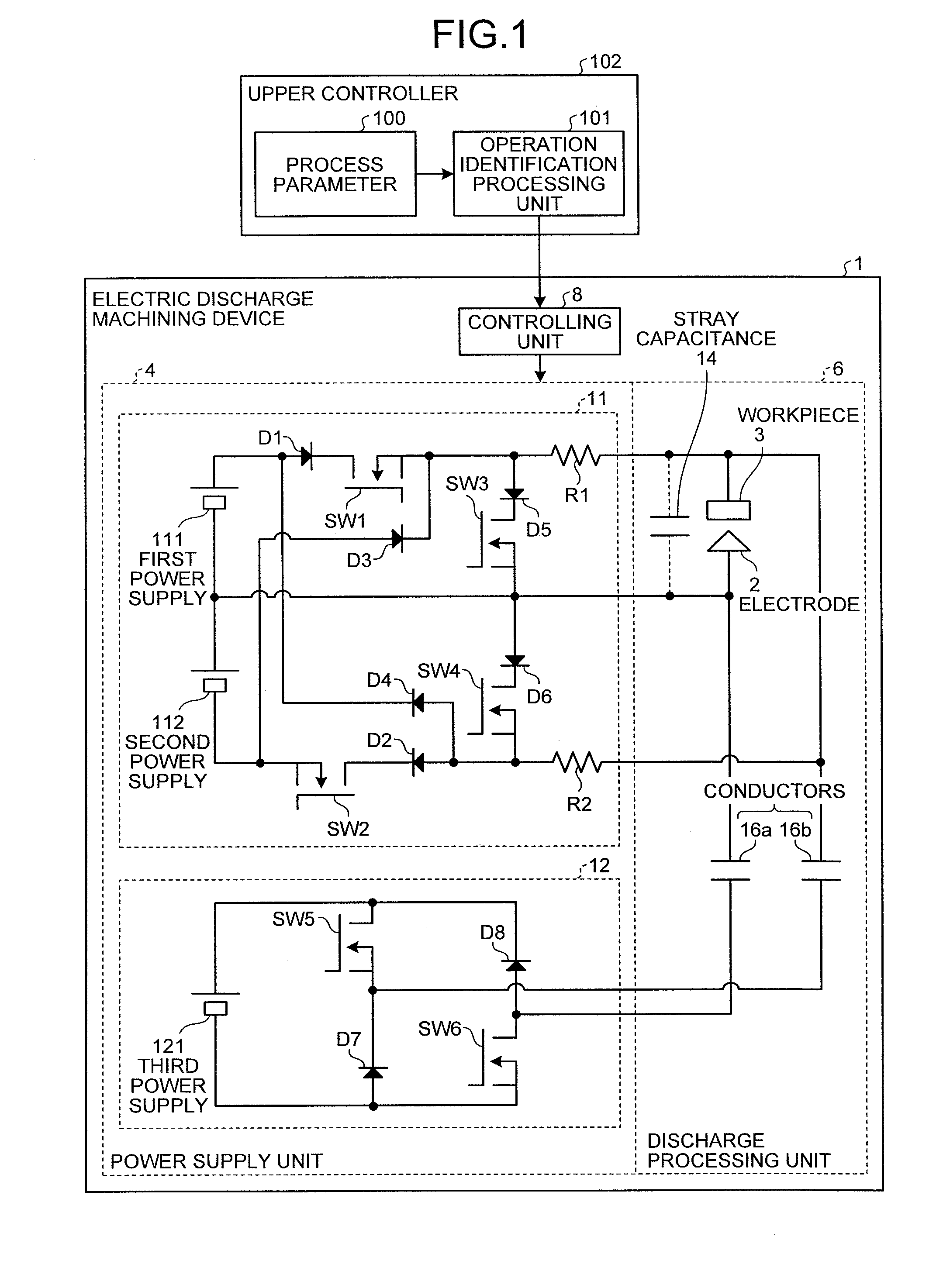
[0045]FIG. 1 is a schematic diagram for showing the structure of an electric discharge machining device according to the first embodiment of the present invention. It is a functional block diagram focusing mainly on the power supply unit. In FIG. 1, an electric discharge machining device 1 includes a power supply unit 4, a discharge processing unit 6, and a controlling unit 8.
[0046](Structure of Electric Discharge Machining Device)
[0047]In FIG. 1, the power supply unit 4 includes a preliminary discharge power supply (also referred to as “auxiliary power supply”) 11 and a main discharge power supply (also referred to as “main power supply”) 12. The preliminary discharge power supply 11 is a power supply that generates a preliminary discharge pulse, which is described later, and includes a first power supply 111 that is the first DC power supply, a second power supply 112 that is the second DC power supply, switching elements SW1 to SW4 that are the first to fourth switches, diodes D1...
second embodiment
Structure of Electric Discharge Machining Device
[0085]FIG. 3 is a schematic diagram for showing the structure of an electric discharge machining device according to the second embodiment of the present invention. According to the first embodiment, the current limiting resistors R1 and R2 are arranged individually in correspondence with the first power supply 111 and the second power supply 112. According to the present embodiment, a shared resistor is provided as a common resistor Rx. The common resistor Rx has one end connected to the electrode 2, and is inserted in the common current path between the electrode 2 and the connection point of the first power supply 111 and the second power supply 112. In this structure, the current flowing from the first power supply 111 and the second power supply 112 to the inter-electrode space can be controlled, and moreover, protection against errors of the switching elements can also be provided. The components that are the same as or produce s...
third embodiment
[0090]FIG. 4 is a schematic diagram for showing the structure of an electric discharge machining device according to the third embodiment of the present invention. According to the first embodiment, the current limiting resistors R1 and R2 are arranged in correspondence with the first power supply 111 and the second power supply 112, respectively, whereas according to the present embodiment, a shared resistor is provided as a common resistor Ry. Furthermore, according to the second embodiment, the common resistor Rx that is shared is inserted between the connection point of the first power supply 111 and the second power supply 112 and the connection point of the switching element SW3 and the diode D6. According to the present embodiment, the common resistor Ry that is shared is inserted between the connection point of the switching element SW3 and the diode D6 and the electrode 2. The components that are the same as or produce similar effects to the components according to the firs...
PUM
| Property | Measurement | Unit |
|---|---|---|
| Current | aaaaa | aaaaa |
Abstract
Description
Claims
Application Information