Gripping assembly and gripping members for a grapple attachment

a technology of gripping assembly and gripping member, which is applied in the direction of drilling casings, load-engaging elements, pipes, etc., can solve the problems of reducing the control and unwanted tilt of the pipe, cumbersome and dangerous, and dangerous for workers, so as to improve the loading and unloading of pipes, reduce manpower, and prevent damage

Active Publication Date: 2010-12-09
LAVALLEY IND
View PDF43 Cites 72 Cited by
  • Summary
  • Abstract
  • Description
  • Claims
  • Application Information

AI Technical Summary

Benefits of technology

[0008]A gripping assembly with gripping members, as part of a grapple attachment, used to grasp and manipulate elongated objects, for example pipe of various diameters and lengths, is described. The gripping attachment is configured to improve loading and unloading of pipe to and from a stack of pipes, for example, on a bed of a truck, rail car or pipe rack with minimal disturbance of or damaging of adjacent pipes or the pipe coating while providing control over the positioning of the pipe, as well as permit controlled laying of pipe, while reducing manpower and eliminating the need for precise centering of the gripping assembly on the pipe. Due to the gripping action of the gripping members and tilt, rotation and shift control capabilities of the grapple attachment, total positive control of the pipe is maintained, even if the gripping assembly picks up the pipe off center. The grapple attachment is able to be used on all pipe surface types, including pipe surfaces that are dirty, or snow or ice covered. The gripping members are configured to prevent damage, not only to the pipe being manipulated, but to adjacent pipes. The gripping members are configured so that the gripping pressure will not crush the pipe.
[0009]The gripping members are used at least in pairs and are mounted on a common main beam structure so that they are separated from each other. The gripping members are interchangeable with other gripping members to permit the grapple attachment to grasp different sized objects, thereby providing modularity to the grapple attachment.
[0011]In one embodiment, the gripping members are configured to be adjustable together to change their position on the main beam structure while maintaining the distance between the gripping members. In another embodiment, one or more of the gripping members are adjustable on the main beam structure in order to alter the distance between the gripping members. In another embodiment, the gripping members are fixedly attached to the main beam structure. As an alternative, the main beam structure can be configured to be adjustable in length, thereby altering the distance between the gripping members, or altering the positions of the gripping members while maintaining the distance therebetween. In addition, the main beam structure can be configured so that it moves on the longitudinal axis in relation to the swivel assembly.
[0017]The gripping members described herein provide a more precise fit around the pipe. There is positive total control of the pipe and no free direction of movement due to the elimination of unwanted swing and tilt.

Problems solved by technology

This is important since being off-center, even by a few inches, results in decreased control and unwanted tilt of the pipe.
This is cumbersome and dangerous which requires three or more workers (excavator operators and two pipe workers).
When unloading the pipe from the truck in this manner, it is dangerous for the worker as the worker can easily fall off of the truck or be hit by or crushed by the pipe.
Even so, it is not uncommon for pipes to be knocked free of the pipe pile, causing dangerous conditions or damaging the pipe.
This tipping movement can break the vacuum seal between the vacuum lift and the pipe or result in dangerous tilting and loss of control of the pipe.
In addition, loss of suction or vacuum power can result in release of the pipe from the vacuum lift resulting in dangerous conditions.

Method used


Image

  • Gripping assembly and gripping members for a grapple attachment
  • Gripping assembly and gripping members for a grapple attachment
  • Gripping assembly and gripping members for a grapple attachment

Examples


Embodiment Construction

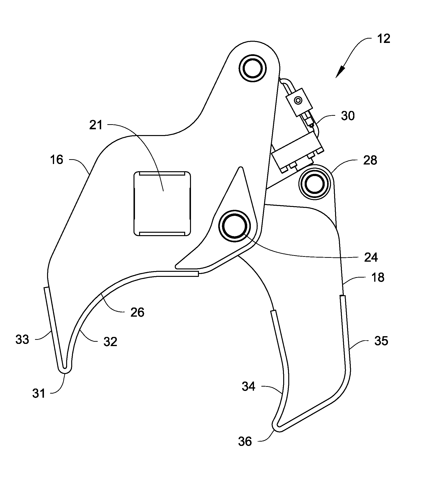
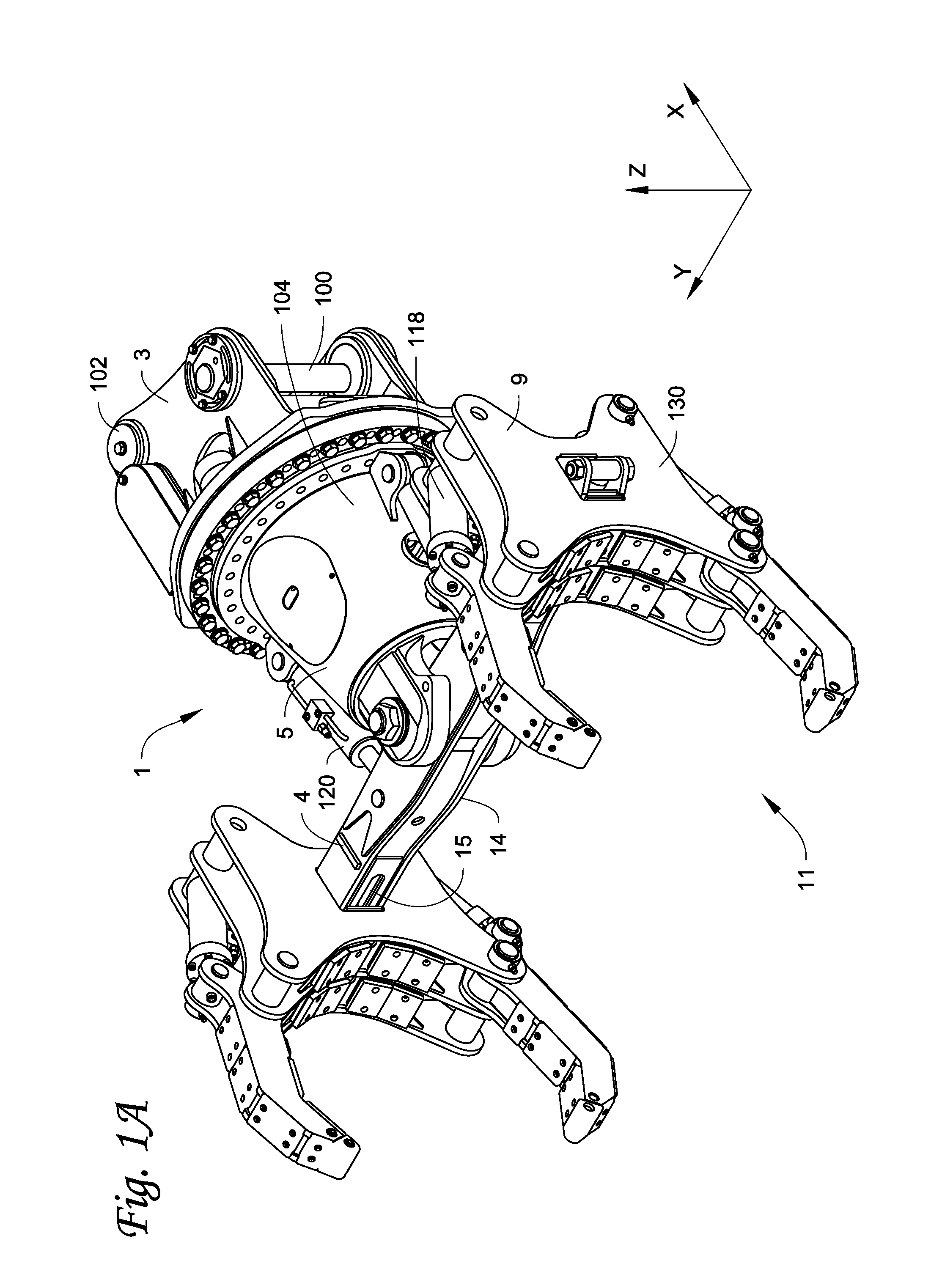
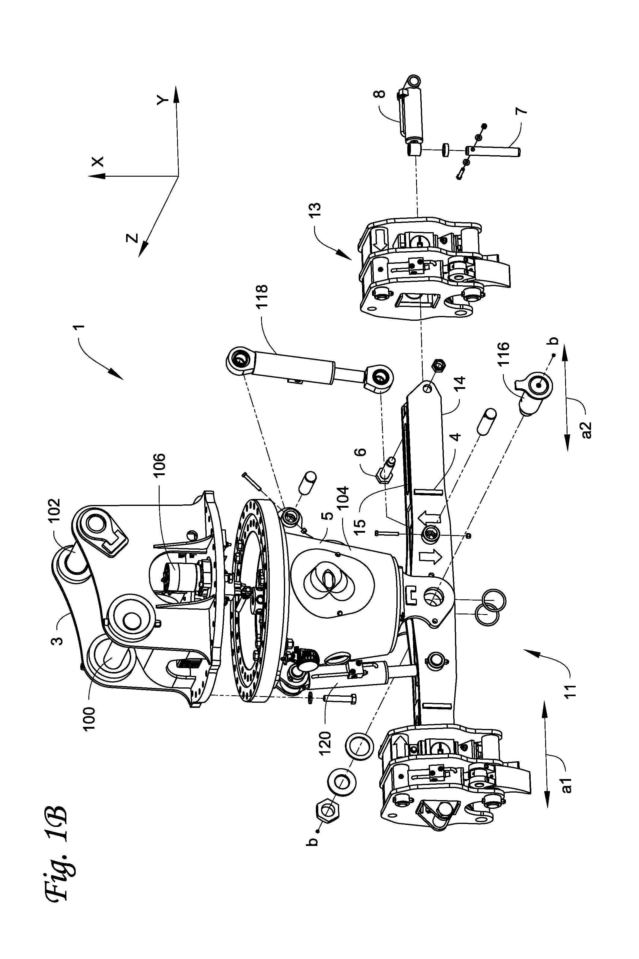
[0029]A gripping assembly with gripping members, as part of a grapple attachment, used to grasp and manipulate elongated objects, for example pipe, is described. Throughout this specification, for ease of discussion and clarity, reference and description will be made to the objects as being pipe. The described grapple attachment can be used in the pipeline construction industry to grasp and manipulate pipe of varying diameters, including large diameter pipe, for example 20 inch pipe, but can be used in other industries as well, such as the logging industry, to grasp other objects. It is to be understood that the concepts as described herein can be equally applied to the grasping and manipulating of any elongated objects, whether cylindrical or non-cylindrical, for example pipes, cylindrical tubes, trees, I-beams, square tubes, triangular tubes, etc.

[0030]The grapple attachment allows for the picking of pipe from, and placement of pipe on, a stack of pipes without disturbing or damag...


PUM


Abstract

A gripping assembly with gripping members, as part of a grapple attachment, used to grasp and manipulate elongated objects, for example pipe, is described. Due to the gripping action of the gripping members and tilt control capabilities of the grapple attachment, total positive control of the pipe is maintained, even if the gripping assembly picks up pipe off center. The grapple attachment is able to be used on all pipe surface types, including pipe surfaces that are dirty, snow or ice covered. The gripping members are configured to prevent damage to the pipe and to adjacent pipes, and will not crush the pipe.

Description

[0001]This application is a continuation-in-part of U.S. patent application Ser. No. 12 / 201,897, filed on Aug. 29, 2008, which claims the benefit of U.S. Provisional Application No. 60 / 969,418, filed Aug. 31, 2007, each of which is incorporated by reference herein in its entirety.FIELD[0002]This disclosure relates to a gripping assembly with gripping members, as part of a grapple attachment, for grasping and manipulating elongated objects, for example cylindrical elongated objects such as pipes, tubes, trees, etc. or non-cylindrical objects such as I-beams, rectangular or square tubing, etc. The grapple attachment is attachable to, for example, a trackhoe, backhoe, excavator or other piece of heavy construction equipment.BACKGROUND[0003]In the construction of pipelines or in directional drilling, it is necessary to load and offload large, unwieldy pipes from flatbed trucks. The weight of a pipe will vary depending on the diameter, wall thickness, and length, with some pipes weighing...

Claims


Application Information

Patent Timeline
Patent Type & Authority Applications(United States)
IPC IPC(8): B66C1/42B66C1/44
CPCE21B19/155E21B19/14B66C1/59B66C3/00B66C3/04
Inventor LAVALLEY, JASONLAVALLEY, ROGERLARSON, MARVINKILPO, LAWRENCE D.BURGESS, MICHAEL
Owner LAVALLEY IND
Why Eureka
Try Eureka