Method of preparing an ophthalmic lens with special machining of its engagement ridge

Active Publication Date: 2010-12-09
ESSILOR INT CIE GEN DOPTIQUE
View PDF3 Cites 18 Cited by
  • Summary
  • Abstract
  • Description
  • Claims
  • Application Information

AI Technical Summary

Benefits of technology

[0019]This compensates the errors inherent to the operation of the reader and shaper appliances not by increasing the accuracy of those appliances, but rather by accommodating said errors by paring away the engagement ridge in singular portions that are particularly sensitive for assembling the lens in its frame.
[0020]These singular portions are zones of interference between the bezel and the surround of the frame when the lens is being engaged in its surround. According to the invention, the positions of these singular portions are derived from the orientation of the second longitudinal profile relative to the frame of reference of the eyeglasses. This derivation may thus be performed easily using a simple calculation algorithm, such that the derivation step may be implemented particularly quickly.
[0021]In these portions, paring aw

Problems solved by technology

Nevertheless, at the end of this feeling operation, errors are observed in the measurement of the shape of the outline.
These errors are inherent to the reader appliance that may present resolution that is not sufficient, or assembly defects, or indeed that may be damaged or out of adjustment.
In addition, while the bezel is being felt, any deformation of the frame (as a result of the feeler bearing against the bezel) likewise give rise to errors.
At the end of the machining operation, edging errors are also observed, such that the actual shape of the edge face of the lens does not correspond exactly to the desired shape.
These errors are likewise inherent to the shaper appliance that may present resolution that is insufficient, or assembly defects, or that may include a grindwheel that is worn in shape.
Furthermore, the bending deformations of the lens (due to the grindwheel bearing against the edge face of the lens while it is being machined) also give rise to errors, as do the phenomena of lenses expanding while they are being machined.
It runs the risk of being either too big, thereby constraining the optician to perform additional and time-consuming machining of the engagement ridge, or too small.
Nevertheless, such methods are lengthy, complex, and expensive to implement.
As a result, the y

Method used


Image

  • Method of preparing an ophthalmic lens with special machining of its engagement ridge
  • Method of preparing an ophthalmic lens with special machining of its engagement ridge
  • Method of preparing an ophthalmic lens with special machining of its engagement ridge

Examples


Embodiment Construction

[0025]The following description with reference to the accompanying drawings given by way of non-limiting example makes it clear what the invention consists in and how it can be reduced to practice.

[0026]In the accompanying drawings:

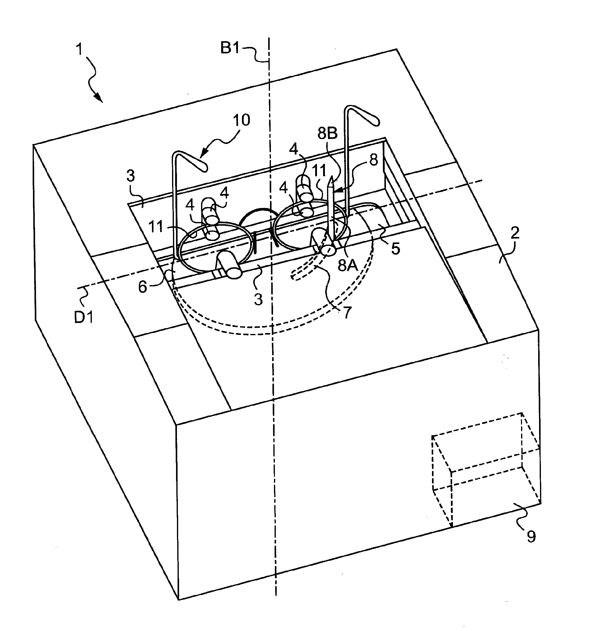
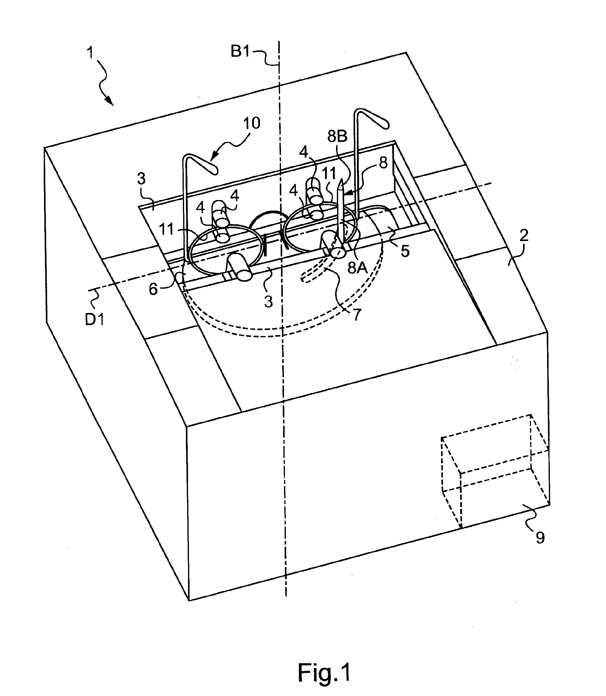
[0027]FIG. 1 is a perspective view of a reader appliance for reading the outline of bezels of eyeglass frames;

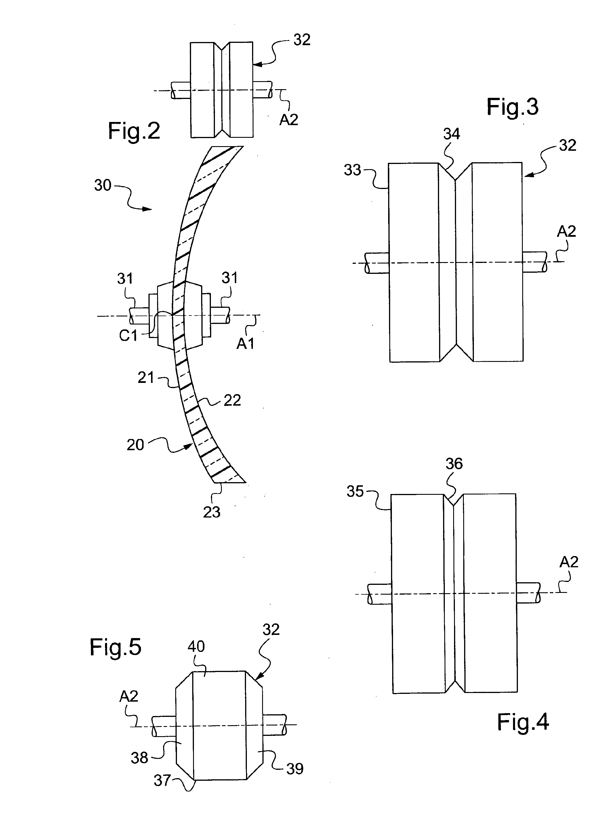
[0028]FIG. 2 is a diagrammatic view of an ophthalmic lens held in a shaper appliance provided with a beveling grindwheel;

[0029]FIGS. 3 to 5 are side views of three beveling grindwheels;

[0030]FIG. 6 is a face view of a non-edged ophthalmic lens, on which there can be seen a longitudinal profile of a bezel of a surround of an eyeglass frame, a longitudinal profile of an engagement ridge that the ophthalmic lens will present once it has been edged, and a boxing frame circumscribing the longitudinal profile of the engagement ridge;

[0031]FIGS. 7A and 7B are section views of the edge faces of two ophthalmic lenses edged using two different implementatio...


PUM


Abstract

A method of preparing an ophthalmic lens for mounting in a surround of an eyeglass frame includes an acquisition step of acquiring a first longitudinal profile of the surround and an orientation parameter of the first longitudinal profile relative to a horizon line or a verticality line of the surround, and an edging step of edging the ophthalmic lens so as to form a generally profiled engagement ridge of desired section that extends along a second longitudinal profile (25) that is derived from the first longitudinal profile and of orientation that is derived from the orientation parameter. The method includes a determination step of determining at least one singular portion (Z1-Z12) of the second longitudinal profile as a function of the orientation parameter. During the edging step, the engagement ridge is locally pared away in the singular portion.

Description

TECHNICAL FIELD TO WHICH THE INVENTION APPLIES[0001]The present invention relates in general to the field of mechanical optics, and more precisely to preparing ophthalmic lenses for engagement in the surrounds of rimmed eyeglass frames.TECHNOLOGICAL BACKGROUND[0002]The technical portion of the profession of an optician consists in mounting a pair of correcting ophthalmic lenses on a rimmed eyeglass frame as selected by a wearer. Such mounting comprises three main operations:[0003]acquiring the shape of the internal outlines of the surrounds of the frame;[0004]centering each lens, which operation consists in positioning and orienting each lens appropriately in front of each eye of a wearer; and then[0005]machining each lens, which consists in cutting out or shaping its outline to the desired shape, taking account of the shapes of the surrounds and of the defined centering parameters.[0006]The specific object of the optician is to edge the ophthalmic lens in such a manner as to enable...

Claims


Application Information

Patent Timeline
IPC IPC(8): G02C7/02
CPCB24B9/14
Inventor HADDADI, AHMED
Owner ESSILOR INT CIE GEN DOPTIQUE
Why Eureka
Try Eureka