Power converter

a power converter and converter technology, applied in the direction of transformers, efficient power electronics conversion, climate sustainability, etc., can solve the problems that the characteristics of switching elements made of silicon have almost reached their theoretical limits, and achieve the effects of reducing cost, reducing conduction loss, and increasing efficiency

Active Publication Date: 2010-12-09
DAIKIN IND LTD
View PDF25 Cites 61 Cited by
  • Summary
  • Abstract
  • Description
  • Claims
  • Application Information

AI Technical Summary

Benefits of technology

[0017]In the power converter of the present invention, since the body diode (131) of switching element (130) is used as a freewheeling diode, it is possible to reduce cost without the need of providing a separate freewheeling diode (132). Further, execution of synchronous rectification enables a reverse current to flow through the switching element (130) and inhibit conduction loss more than the body diode (131) alone does.
[0018]When synchronous rectification is carried out by select

Problems solved by technology

However, the characteristics of switching elements made

Method used


Image

  • Power converter
  • Power converter
  • Power converter

Examples


first embodiment

The First Embodiment

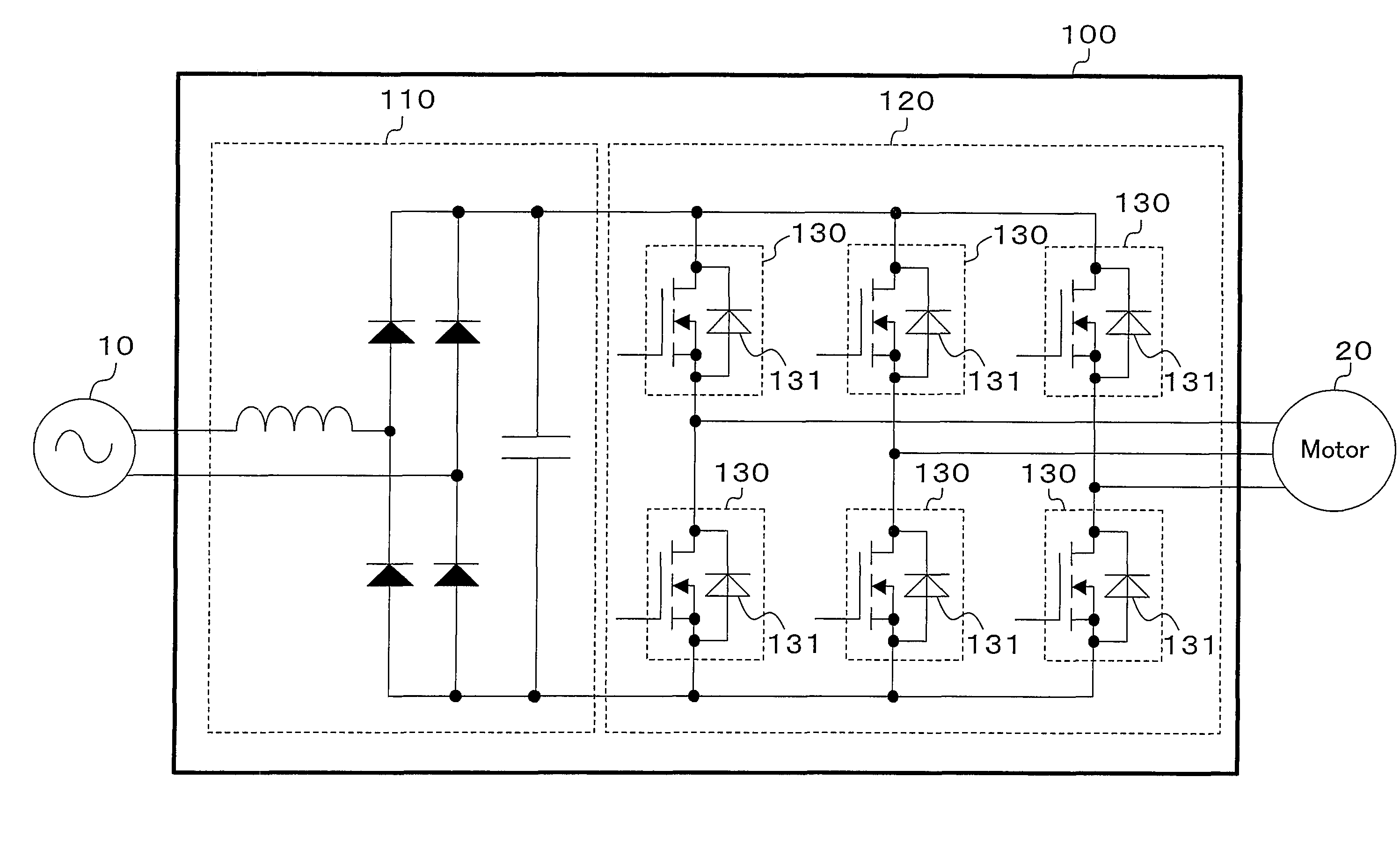
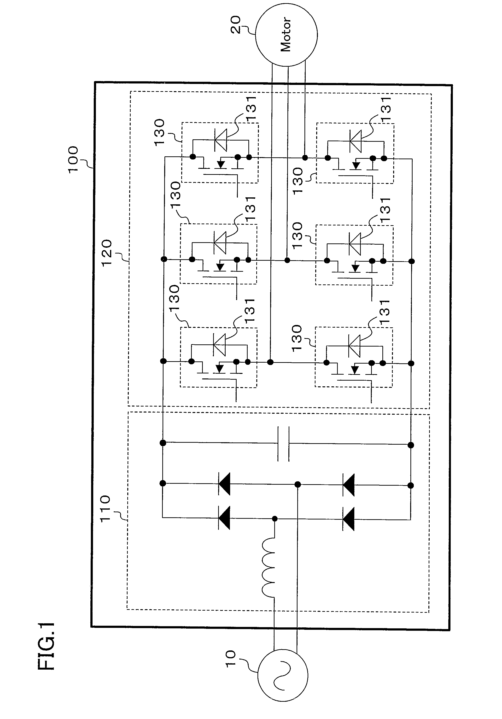
[0036]FIG. 1 shows a configuration of a power converter according to the first embodiment of the present invention. This power converter (100) rectifies alternating voltage of an a.c. power supply (10) using a converter circuit (110) and converts the direct current into a three-phase current by means of an inverter circuit (120) to supply the resultant current to a motor (20). This motor (20) is to drive a compressor that is provided for a refrigerant circuit in an air conditioner. Here, in FIG. 1 the a.c. power supply (10) is assumed to supply a single-phase current, but may supply a three-phase current.

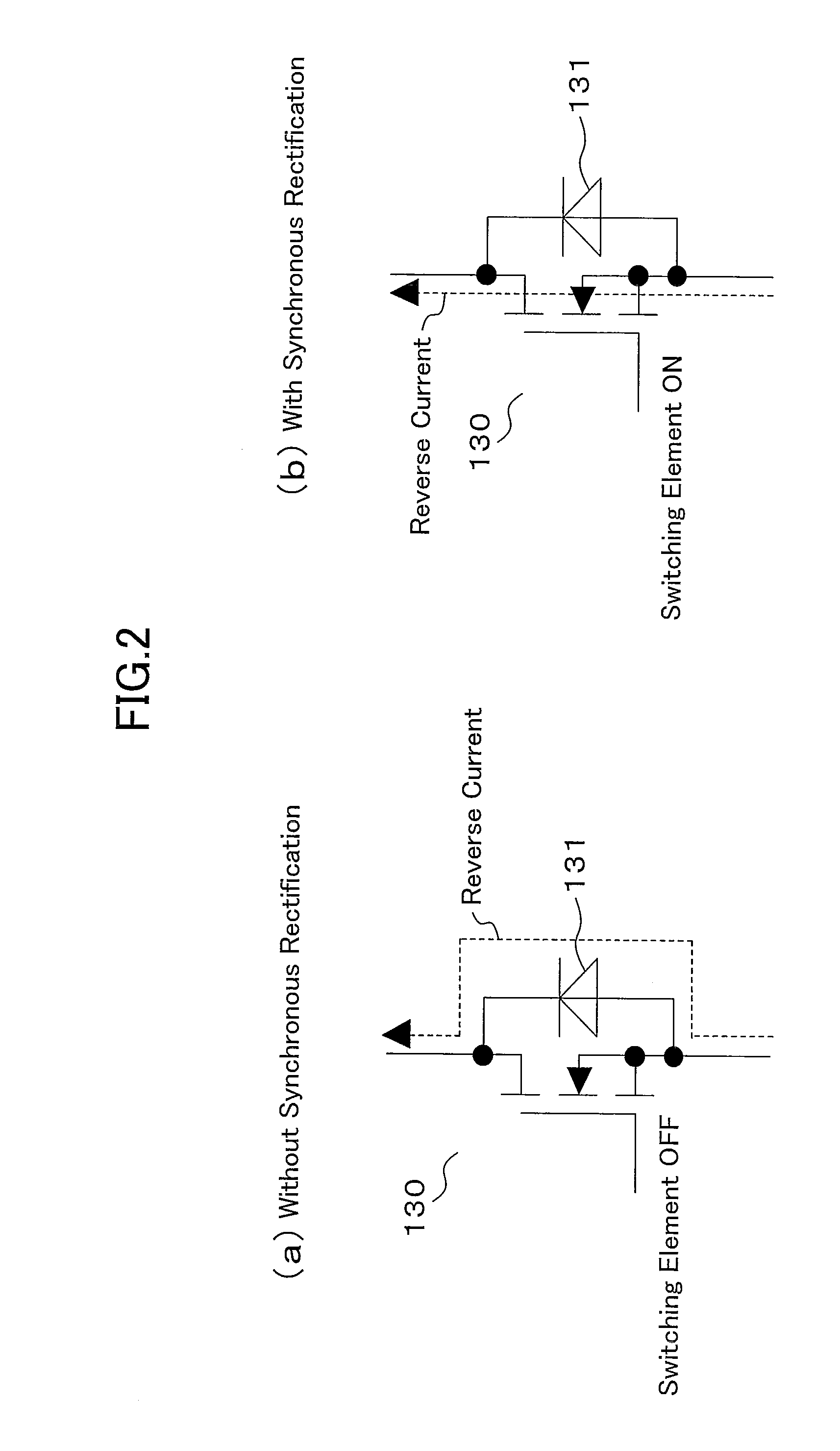
[0037]The inverter circuit (120) is configured such that synchronous rectification is performed by six switching elements (130). The switching element (130) is comprised of a unipolar device (SiC MOSFET herein) using a wideband gap semiconductor. The inverter circuit (120) uses the body diode (131) of the SiC MOSFET (130) as a freewheeling diode when performing s...

second embodiment

The Second Embodiment

[0055]FIG. 5 shows a configuration of a power converter according to the second embodiment of the present invention. This power converter (500) performs synchronous rectification, using the body diode (131) of a SiC MOSFET (130) as the diode for a boosting chopper circuit (111) used as a power factor enhancement circuit. With this synchronous rectification, efficiency is improved, especially under light load conditions. Further, since a SiC device is used, the recovery current is made markedly low compared to that with a Si device so that it is possible to reduce switching loss.

third embodiment

The Third Embodiment

[0056]FIG. 6 shows a configuration of a power converter according to the third embodiment of the present invention. This power converter (600) performs synchronous rectification, using the body diodes (131) in SiC MOSFETs (130) as the rectifying diodes for a converter circuit (110). Though in FIG. 6, a commercial power supply (10) is assumed to be a single-phase alternating current, three-phase alternating current may be used. Further, only part of the rectifying diodes in the converter circuit (110) may use the body diode (131) of the SiC MOSFET (130) while the others may use usual diodes.


PUM


Abstract

An inverter circuit (120) is configured so as to perform synchronous rectification by six switching elements (130). The switching element (130) is formed of an unipolar device (SiC MOSFET in this case) using a wideband gap semiconductor. The inverter circuit (120) uses the body diode (131) of SiC MOSFET (130) as a freewheeling diode during synchronous rectification.

Description

TECHNICAL FIELD[0001]The present invention relates to a power converter having switching elements formed of unipolar devices using a wideband gap semiconductor.BACKGROUND ART[0002]As a material for switching elements for a power converter, silicon are widely used at present. However, the characteristics of switching elements made of silicon have almost reached their theoretical limits. As the materials that exceed the theoretical limit of silicon, there exist wideband gap semiconductors such as SiC (silicon carbide), GaN (gallium nitride) and diamond, the development of these being in progress. Power devices using wideband gap semiconductors have super low-loss and high-speed high-temperature operation characteristics. Of these wideband gap semiconductors, the most remarkable one is the SiC device, and SiC MOSFETs are regarded as promising switching for power converter.[0003]In inverter circuits and the like that drive inductive loads, a diode is connected in parallel with a switchi...

Claims


Application Information

Patent Timeline
IPC IPC(8): H02M7/06
CPCH02M7/5387H02M7/797Y02B70/1483H03K17/08142Y02B70/1408H02M2007/2195H02M1/4225H02M5/297H02M7/219H02M5/293H02M5/458H02M5/4585H02M1/0051H02M7/2195Y02B70/10H01L21/18H02M7/21
Inventor MAEDA, TOSHIYUKISEKIMOTO, MORIMITSUHIBINO, HIROSHI
Owner DAIKIN IND LTD
Why Eureka
Try Eureka