Method and System for a Voltage-Controlled Oscillator with a Leaky Wave Antenna

a leaky wave antenna and voltage control technology, applied in pulse manipulation, pulse technique, instruments, etc., can solve the problem that transmitters and/or receivers are often power inefficient in comparison to other blocks of portable communication devices

Active Publication Date: 2010-12-09
AVAGO TECH INT SALES PTE LTD
View PDF100 Cites 46 Cited by
  • Summary
  • Abstract
  • Description
  • Claims
  • Application Information

AI Technical Summary

Benefits of technology

[0018]A system and / or method for a voltage-controlled oscillator with a leaky wave antenna, substantially as shown in and / or described in connection with at least one of the figures, as set forth more completely in the claims.

Problems solved by technology

Additionally, transmit and / or receive circuitry within such mobile wireless devices often account for a significant portion of the power consumed within these devices.
Moreover, in some conventional communication systems, transmitters and / or receivers are often power inefficient in comparison to other blocks of the portable communication devices.

Method used


Image

  • Method and System for a Voltage-Controlled Oscillator with a Leaky Wave Antenna
  • Method and System for a Voltage-Controlled Oscillator with a Leaky Wave Antenna
  • Method and System for a Voltage-Controlled Oscillator with a Leaky Wave Antenna

Examples


Embodiment Construction

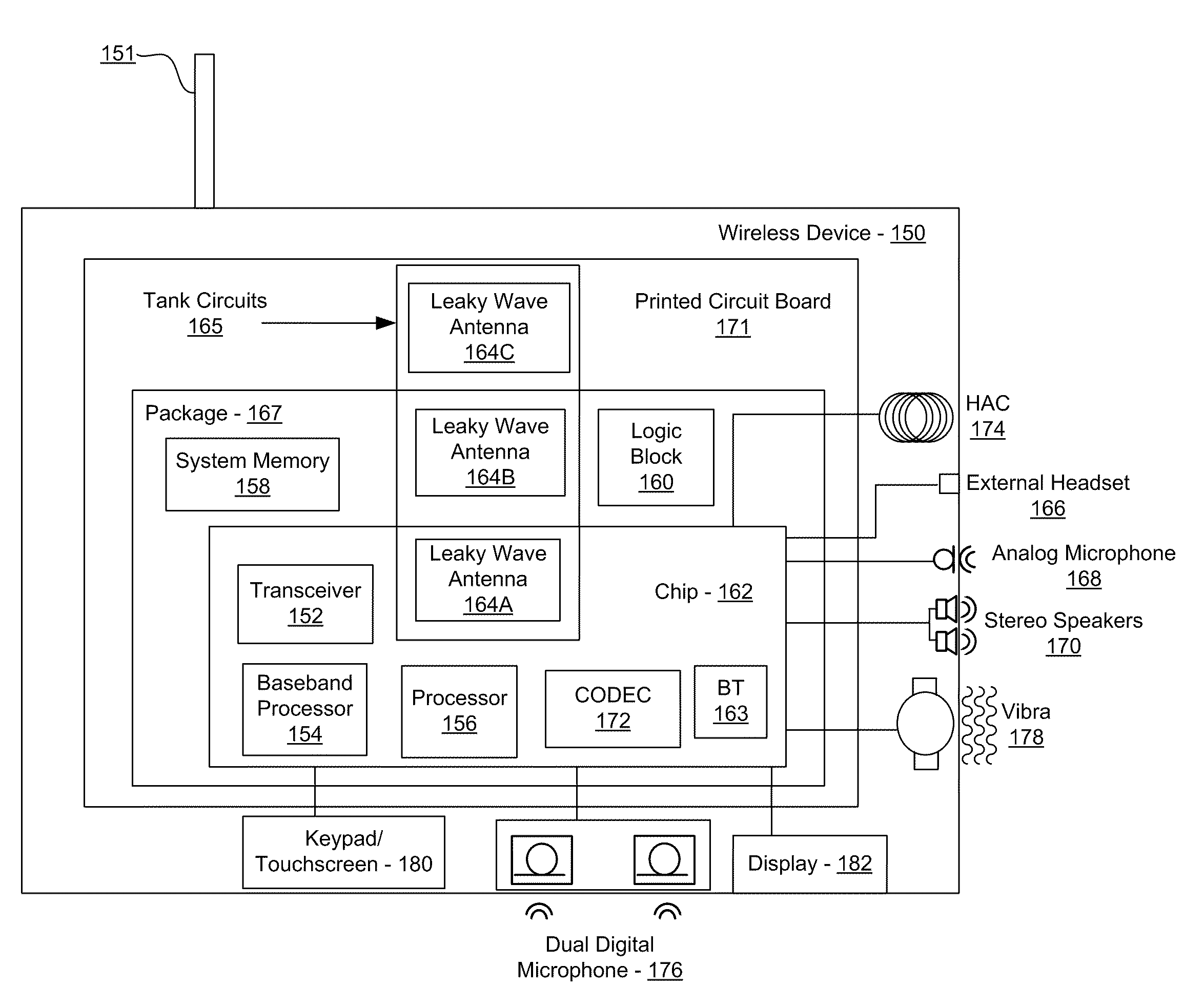
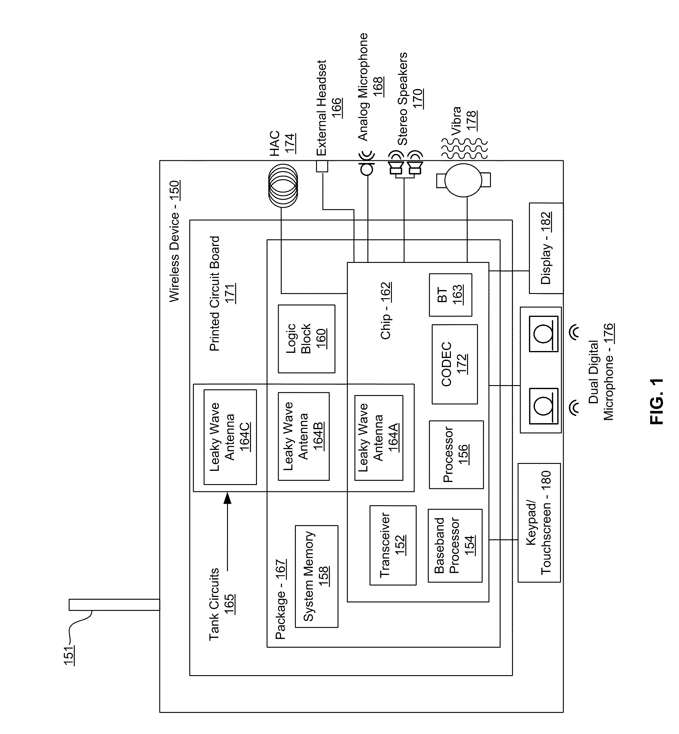
[0029]Certain aspects of the invention may be found in a method and system for a voltage-controlled oscillator with a leaky wave antenna. Exemplary aspects of the invention may comprise transmitting wireless signals via one or more leaky wave antennas in one or more tank circuits coupled to one or more VCOs. The VCOs may be two-point modulated. Two modulating signals may be communicated to the one or more VCOs via varactors coupled to tank circuits on the one or more VCOs. The varactors may comprise CMOS transistors with source and drain terminals that are shorted together. The one or more leaky wave antennas may be integrated on the chip, on a package to which the chip is affixed, or on a printed circuit board to which the chip is affixed. The VCOs may be integrated in a phase-locked loop and an output of the one or more VCOs in the phase-locked loop may be fed back via a multi-modulus detector.

[0030]FIG. 1 is a block diagram of an exemplary wireless system utilizing leaky wave ant...


PUM


Abstract

Methods and systems for a voltage-controlled oscillator (VCO) with a leaky wave antenna are disclosed and may include transmitting wireless signals via one or more leaky wave antennas in one or more tank circuits coupled to one or more VCOs. The VCOs may be two-point modulated. Two modulating signals may be communicated to the one or more VCOs via varactors coupled to tank circuits on the one or more VCOs. The varactors may include CMOS transistors with source and drain terminals shorted together. The one or more leaky wave antennas may be integrated on the chip, on a package to which the chip is affixed, or on a printed circuit board to which the chip is affixed. The VCOs may be integrated in a phase-locked loop and an output of the one or more VCOs in the phase-locked loop may be fed back via a multi-modulus detector.

Description

CROSS-REFERENCE TO RELATED APPLICATIONS / INCORPORATION BY REFERENCE[0001]This application makes reference to and claims priority to U.S. Provisional Application Ser. No. 61 / 246,618 filed on Sep. 29, 2009, and U.S. Provisional Application Ser. No. 61 / 185,245 filed on Jun. 9, 2009.[0002]This application also makes reference to:[0003]U.S. patent application Ser. No. ______ (Attorney Docket No. 21181US02) filed on even date herewith;[0004]U.S. patent application Ser. No. ______ (Attorney Docket No. 21205US02) filed on even date herewith;[0005]U.S. patent application Ser. No. ______ (Attorney Docket No. 21211US02) filed on even date herewith;[0006]U.S. patent application Ser. No. ______ (Attorney Docket No. 21214US02) filed on even date herewith;[0007]U.S. patent application Ser. No. ______ (Attorney Docket No. 21230US02) filed on even date herewith;[0008]U.S. patent application Ser. No. ______ (Attorney Docket No. 21231 US02) filed on even date herewith;[0009]U.S. patent application Ser....

Claims


Application Information

Patent Timeline
Patent Type & Authority Applications(United States)
IPC IPC(8): H04B1/10H03K5/00
CPCH01Q1/2283H01Q13/22H04B5/0031H01Q15/006G01S13/06H01Q13/20H04B1/04H04B7/24H04B1/0458H01L2224/16225H01L2224/32225H01L2224/73204H01L2924/13091H01L2924/00G06K7/10316H01Q15/0066H01Q15/23H01Q19/06
Inventor ROFOUGARAN, AHMADREZAROFOUGARAN, MARYAM
Owner AVAGO TECH INT SALES PTE LTD
Why Eureka
Try Eureka