[0009]In another aspect, detecting faults may include detecting, based upon the regulator control signals and the status signals that indicate status of the pressure switch, that the electro-hydraulic control system failed to increase the main line pressure above a threshold pressure level associated with the pressure switch, and generating one or more diagnostic signals may includes generating one or more diagnostic signals that indicate the electro-hydraulic control system failed to increase the main line pressure above the threshold pressure level. Detecting faults may also include detecting fluid leakage based upon the regulator control signals and the status signals that indicate status of the pressure switch, and generating one or more diagnostic signals may include generating one or more diagnostic signals that indicate fluid leakage detected. Detecting faults may also include detecting, based upon the regulator control signals and the status signals that indicate status of the pressure switch, that the electro-hydraulic control system failed to decrease the main line pressure below a threshold pressure level associated with the pressure switch, and generating one or more diagnostic signals may include generating one or more diagnostic signals that indicate the electro-hydraulic control system failed to decrease the main line pressure below the threshold pressure level.
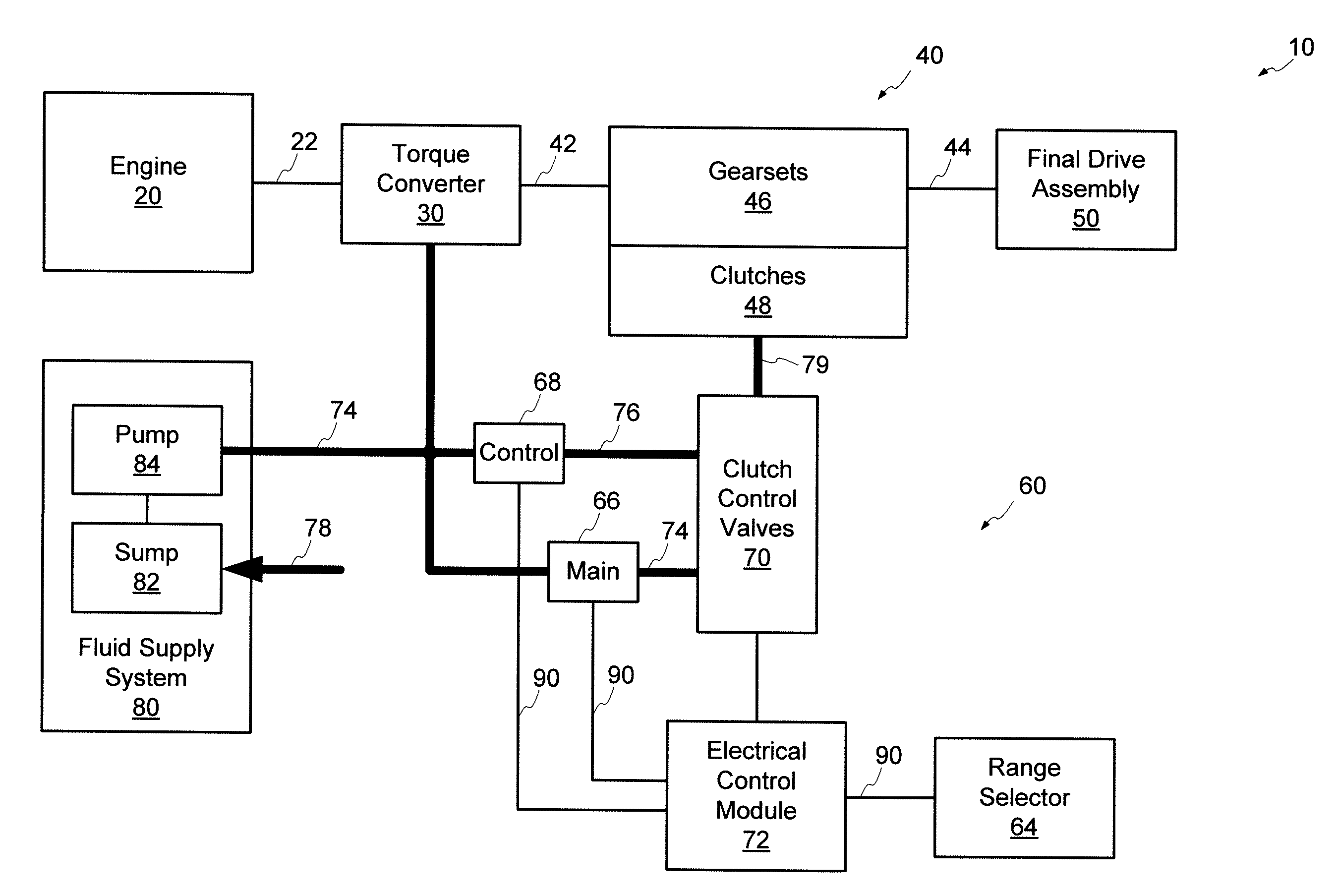
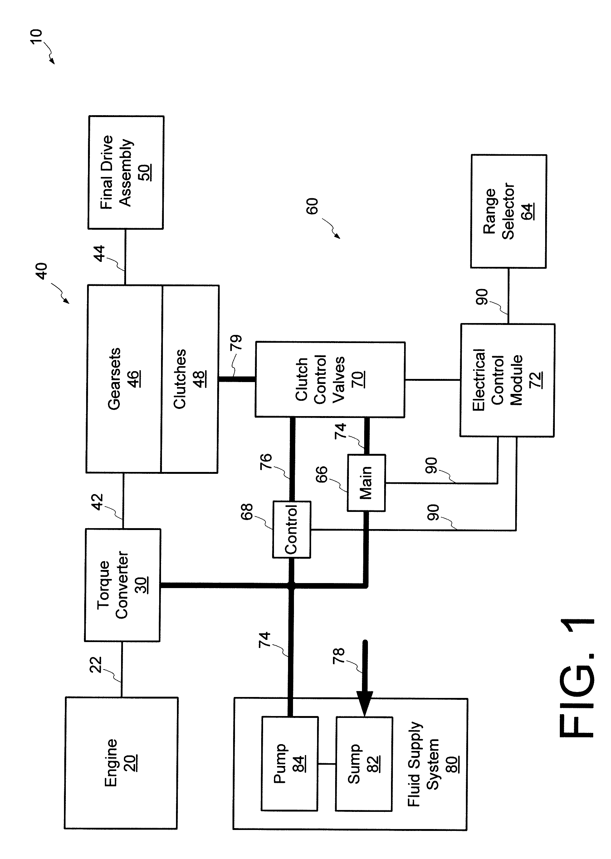
[0010]In yet another aspect, an electro-hydraulic control system for a transmission includes a pressure switch, a plurality of valves, and an electronic control module. The pressure switch receives fluid, opens in response to a pressure level of the fluid being greater than a threshold pressure level, closes in response to the pressure of the fluid being less than the threshold pressure level, and generates a status signal that indicates status of the pressure switch. The plurality of valves develop a main line pressure based upon regulator control signals, develop a control main pressure based upon the main line pressure, and develop a clutch feed pressure based upon clutch control signals, the main line pressure, and the control main pressure. The plurality of valves further selectively deliver fluid at the control main pressure to the pressure switch based upon a pressure level of the main line pressure. The electronic control module generates regulator control signals to control the main line pressure, generates clutch control signals to control the clutch feed pressure, and detects faults based upon regulator control signals and status signals of the pressure switch.
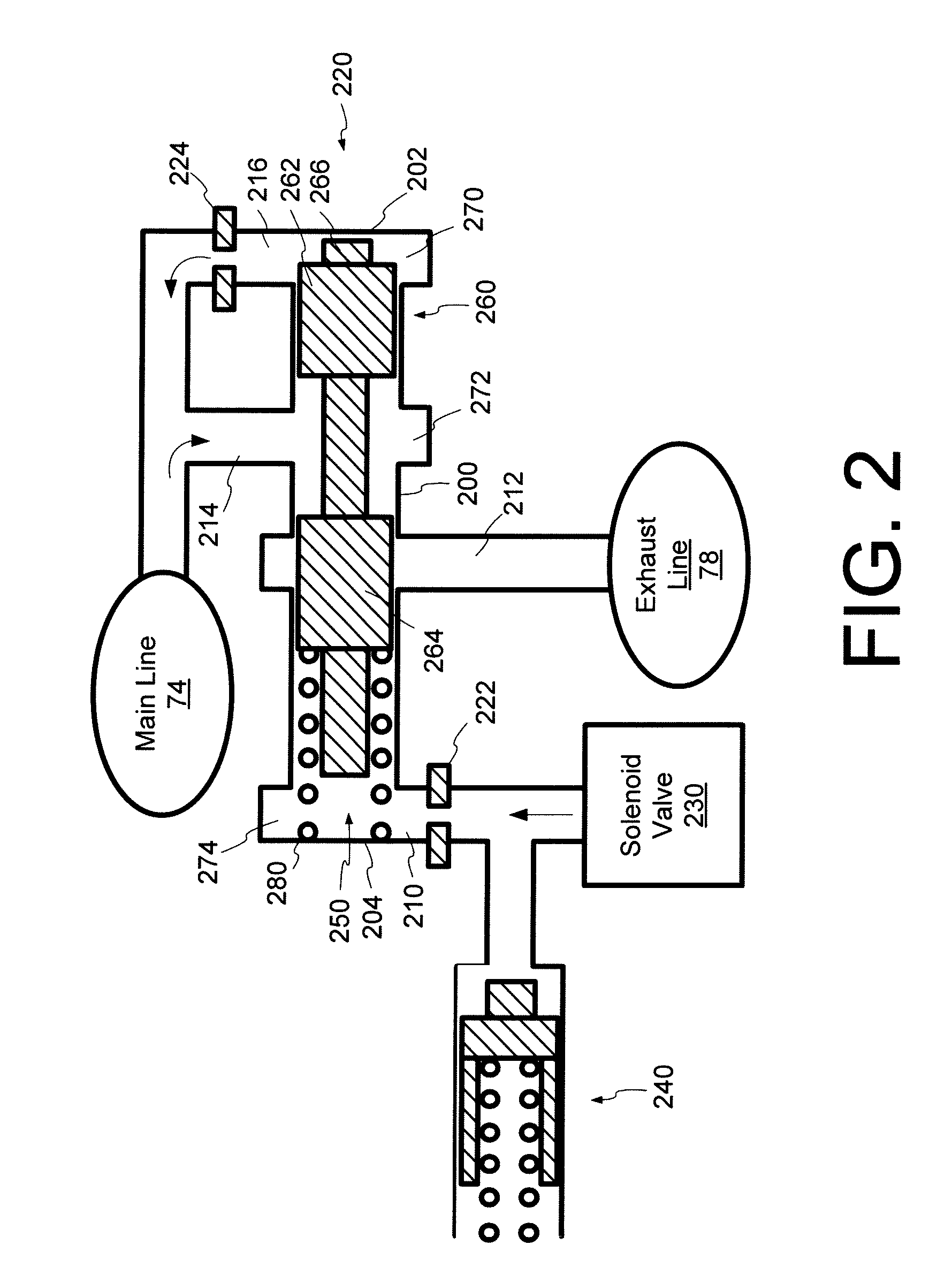
[0011]In some aspects, the plurality of valves includes a control main valve to develop the control main pressure. The control main valve includes a port to receive the main line pressure, and a port to supply fluid at the control main pressure in response to receiving the main line pressure. The control main valve further includes the pressure switch and a valve member that selectively directs the control main pressure to the pressure switch based upon a pressure level of the main line pressure.
[0012]In other aspect, the plurality of valves includes a clutch trim valve to develop the clutch feed pressure based upon clutch control signals, the main line pressure, and the control main pressure. The clutch trim valve includes a port to receive the main line pressure, and a port to receive the control main pressure, and a port to supply the clutch feed pressure. The control main valve further includes the pressure switch and a valve member that selectively directs the control main pressure to the pressure switch based upon a pressure level of the main line pressure.
[0013]In some aspects, the electronic control module adjusts regulator control signal to increase the main line pressure from a nominal level to a first pressure level, and detects a fault in response to status signals indicating the pressure switch is open and regulator control signals requested the main line pressure be increased to the first pressure level. The electronic control module may further adjust regulator control signals to increase the main line pressure from the first pressure level to a second pressure level, and may detect a fault in response to status signals indicating the pressure switch is closed and regulator control signals requested the main line pressure be increased to the second pressure level. The electronic control module may further adjust regulator control signals to reduce the main line pressure from the second pressure level to a third pressure level, and may detect a fault in response to status signals indicating the pressure switch is open and regulator control signals requested the main line pressure be decreased to the third pressure level.
[0014]In some aspects, the electronic control module may detect based upon the regulator control signals and the status signals that a fluid supply source failed to deliver fluid. The electronic control module may also detect fluid leakage based upon the regulator control signals and the status signals.

