
System, method, apparatus, device and computer program product for automatically detecting positioning effect

Active Publication Date: 2010-12-09
SAFEOP SURGICAL
View PDF16 Cites 22 Cited by
  • Summary
  • Abstract
  • Description
  • Claims
  • Application Information

AI Technical Summary

Benefits of technology

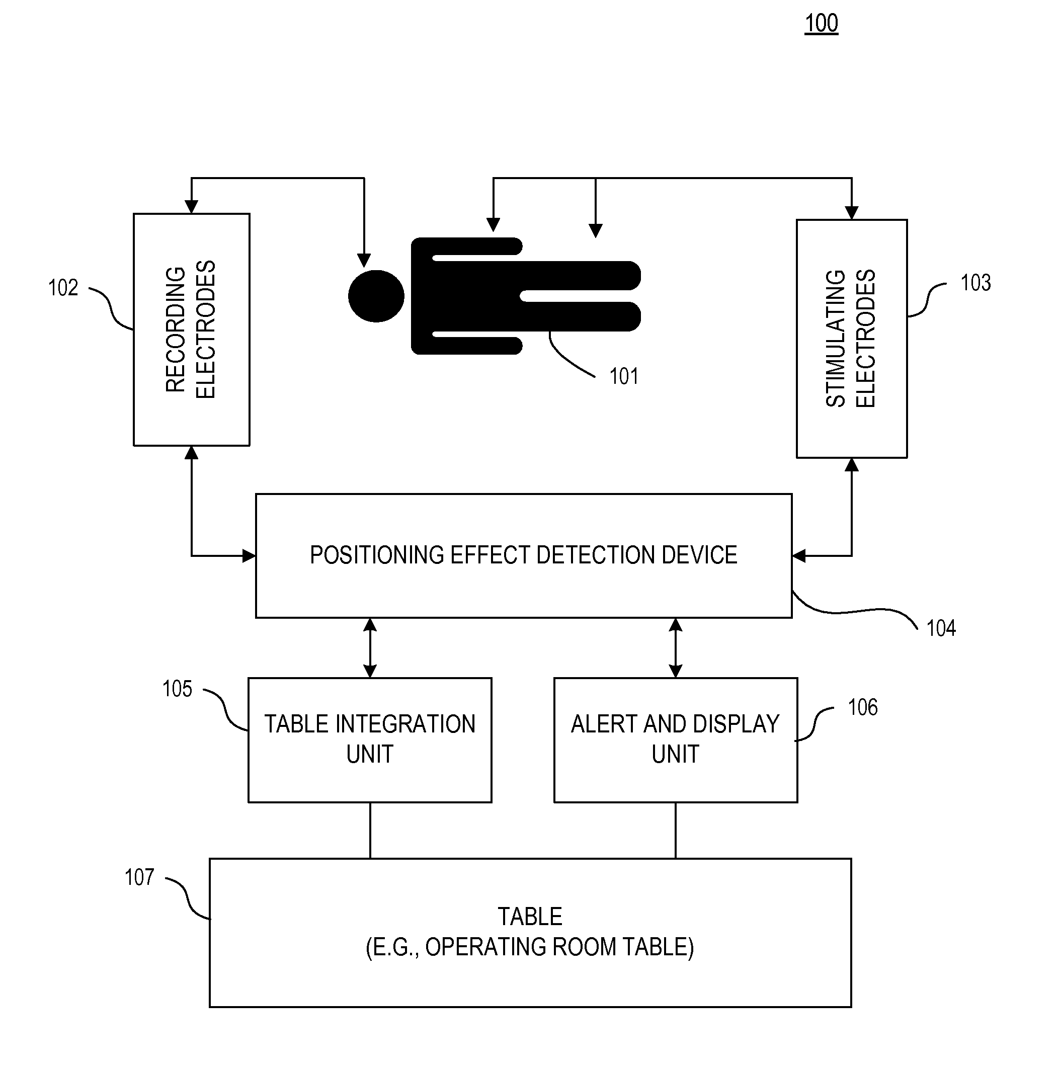
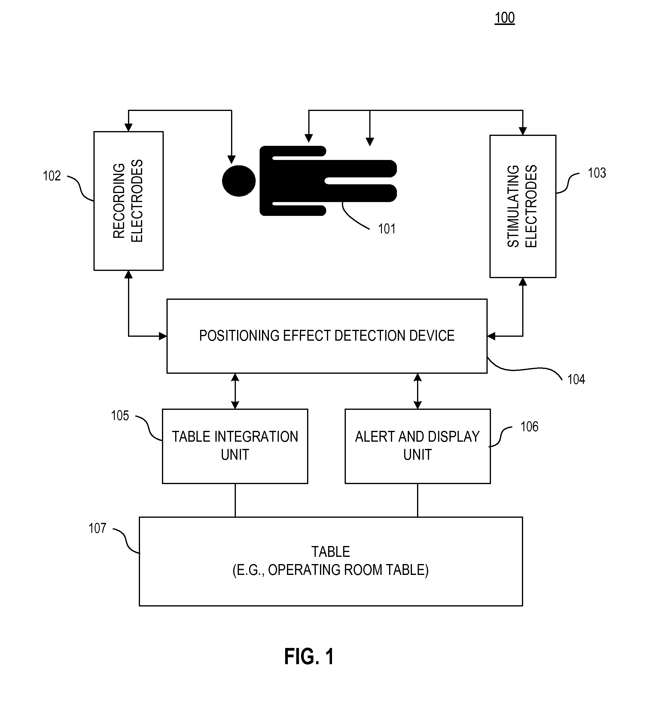
[0005]According to an exemplary embodiment, a method of identifying positioning effect in a patient may be provided. According to an exemplary embodiment, the method may include stimulating one or more peripheral nerves with one or more electrical pulses from one or more stimulating electrodes, recording resultant electrical waveforms generated by a nervous system of the patient in response to the electrical pulses using one or more recording electrodes, and identifying, by or with one or more computing devices, the positioning effect based on the resultant electrical waveforms.
[0010]According to an exemplary embodiment, the method may further include determining how to reduce the positioning effect based on a position of a table.
[0012]According to an exemplary embodiment, the method may further include providing information to a table to at least partially reposition the table to reduce the positioning effect.
[0018]According to an exemplary embodiment, the processor may further include means for identifying the positioning effect which may include one or more means for identifying changes in a latency of the resultant electrical waveforms, means for identifying changes in an amplitude of the resultant electrical waveforms, and / or means for identifying changes in a morphology of the resultant electrical waveforms.
[0022]According to an exemplary embodiment, the interface may be operable to transfer information between the table and the one or more processors to reduce the positioning effect.

Problems solved by technology

Therefore, they would be unable to identify the usual warning signs resulting from positioning effect.
Continued trauma from positioning effect may result in prolonged or even permanent injury.

Method used


Image

  • System, method, apparatus, device and computer program product for automatically detecting positioning effect
  • System, method, apparatus, device and computer program product for automatically detecting positioning effect
  • System, method, apparatus, device and computer program product for automatically detecting positioning effect

Examples


table embodiment

Exemplary Operating Room Table Embodiment

[0082]FIG. 3 depicts an exemplary diagram of the table 107, according to an exemplary embodiment of the present invention. According to an exemplary embodiment, the table 107 may include parts operable to move the patient. In an exemplary embodiment, the table 107 may include, e.g., but not limited to, a head piece 302, a torso piece 304, one or more arm pieces 306A, 306B, and a leg piece 308. According to an exemplary embodiment, the table 107 may use parts of the table to move body parts of a patient, such as, e.g., but not limited to, the patient's head, the patient's arms, the patient's legs, etc., individually or in combination. In an exemplary embodiment, the table 107 may position a patient, such as, e.g., but not limited to, tilt, rotate, flex, reflex, incline, decline, etc. According to an exemplary embodiment, the table 107 may include an interface 310 operable to receive instructions from a user to position the table 107. According...


PUM


Abstract

An automated system, method, apparatus, device and / or computer program product for detecting positioning effect is set forth, the apparatus according to an exemplary embodiment may include an output operable to couple to one or more stimulating electrodes to stimulate one or more peripheral nerves of the patient, an input operable to couple to one or more recording electrodes to record resultant electrical waveforms generated by a nervous system of a patient in response to the stimulating module, and one or more processors operable to identify the positioning effect based on the resultant electrical waveforms.

Description

CROSS-REFERENCE TO RELATED APPLICATION[0001]This application claims priority to U.S. Provisional Application No. 61 / 185,441 filed Jun. 9, 2009, the entire contents of which are hereby incorporated by reference.FIELD OF THE INVENTION[0002]The present invention relates to a medical device, and more particularly to a device for injury detection.BACKGROUND[0003]During many types of surgeries, patients are positioned, e.g., by medical workers, to facilitate surgical access in ways that may put undue tension or pressure on peripheral nervous structures. This undue tension or pressure can create what is generally termed as a “positioning effect.” Warning signs of positioning effect may include sensations, such as, e.g., but not limited to, numbness, tingling or weakness. During surgery, a patient is usually placed under general anesthesia. Therefore, they would be unable to identify the usual warning signs resulting from positioning effect. Consequentially, the patient would be left in thi...

Claims


Application Information

Patent Timeline
IPC IPC(8): A61B5/103A61B5/02
CPCA61B5/04001A61G13/10A61B5/04A61B5/4821A61B5/4893A61B5/1106A61G13/0036A61B5/4041A61B5/7203A61B5/7275A61B5/742A61B5/746A61G13/12A61B5/24A61B5/388
Inventor JOHNSON, SAMUELO'BRIEN, RICHARD A.
Owner SAFEOP SURGICAL
Learn More