
Portable electronic device holster with guided docking station

a portable electronic device and docking station technology, applied in the field of holsters, can solve the problems of cumbersome and detracting power supply interfaces, difficult to insert or retrieve devices, and rotate the holster, and achieve the effect of convenient and reliable insertion and removal

Inactive Publication Date: 2010-12-09
STAMPFLI URS
View PDF25 Cites 31 Cited by
  • Summary
  • Abstract
  • Description
  • Claims
  • Application Information

AI Technical Summary

Benefits of technology

[0008]It is another object of the invention to provide an interface for reliably and readily connecting a portable electronic device to power sources while making insertion and retrieval into the holster easy and convenient.
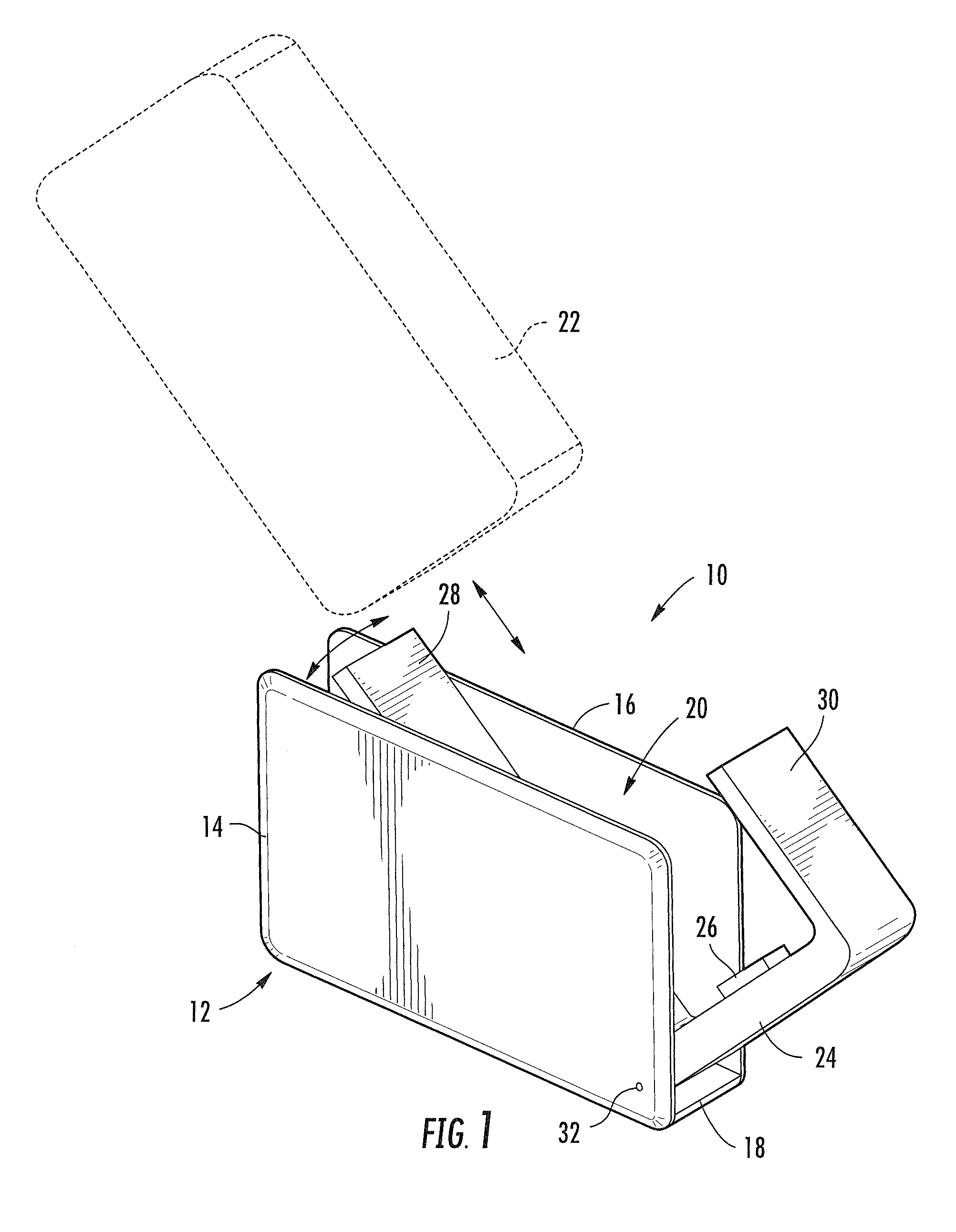
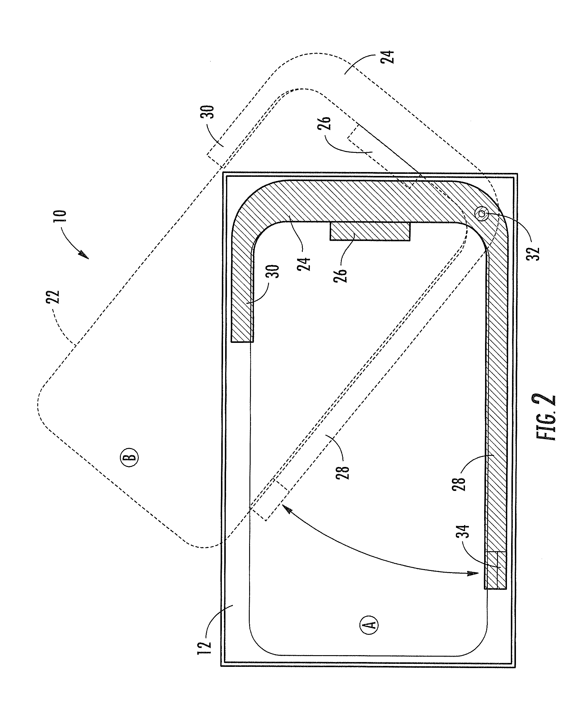
[0012]According to further aspects of the invention, the docking station is pivotally mounted to the carrier so that the docking station and guide rails can pivot relative to the carrier. As a result, a portable electronic device can be more easily and reliably inserted into and removed from the docking station. At least one of the guide rails can be adjustably connected to the docking station so that the spacing between the guide rails can be selectively changed to accommodate portable electronic devices of different sizes. Further, at least one of the guide rails can provide a releasable lock for locking the docking station and guide rails in the stored position.

Problems solved by technology

The placement of the opening sometimes makes it difficult to insert or retrieve the device, particularly, when worn at the waist on a belt.
However, such rotating clip can also present the danger that the holster is rotated inadvertently through user movement to dump the device out of the holster onto the ground.
Some holsters have solar cell charging surfaces integrated on to the carrier exterior surfaces, but the interfaces to supply the power to the devices can be cumbersome and detract from the primary function of ease of insertion and retrieval into the holster as a storage device.

Method used


Image

  • Portable electronic device holster with guided docking station
  • Portable electronic device holster with guided docking station
  • Portable electronic device holster with guided docking station

Examples


Embodiment Construction

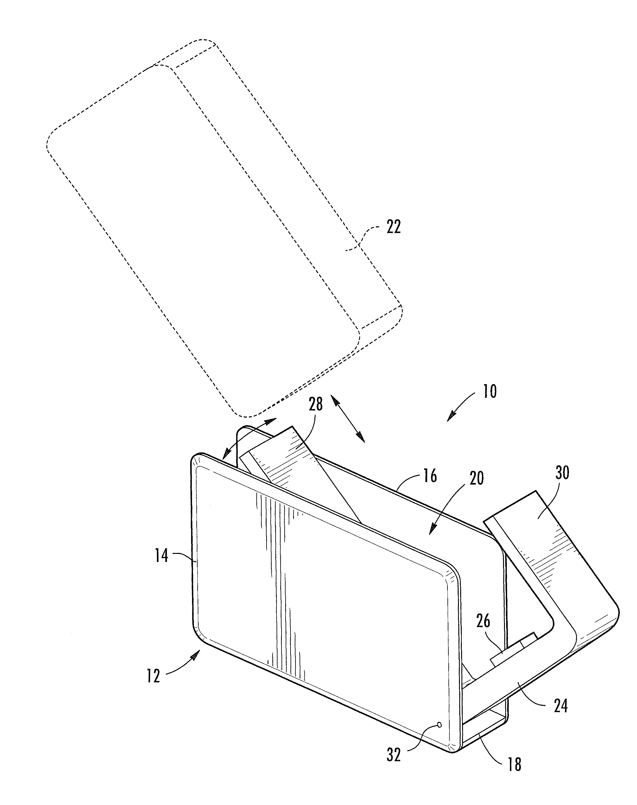
[0033]Referring to FIG. 1, one embodiment of a holster 10 having features according to aspects of the invention is shown. The holster 10 can include a carrier 12 having at least two spaced apart side walls 14, 16 and a base 18 joining the two side walls 14, 16 to provide a storage space 20 for a portable electronic device 22, such as a cellular phone, personal digital assistant or a digital audio device, to name a few examples. The holster 10 can also include a docking station 24 having electrical contacts for interfacing with electrical contacts of a portable electronic device 22. The electrical contacts can be provided, for example, through a multi-contact port 26, that can interface with a matching port on the device 22. The docking station 24 can be mounted to the carrier 12 in the storage space 20. Two spaced apart guide rails 28, 30 can extend from the docking station 24 for engaging sides of a portable electronic device 22 and guiding it into electrical contact with the docki...


PUM


Abstract

A holster provides a carrier for removable storing a portable electronic device, such as a cellular phone, PDA or MP3 player, and a fastener for securing the carrier to the user's clothing or bag. The holster includes a docking station inside the carrier and a pair of guide rails extending from the docking station to guide a device into electrical contact with the docking station. The docking station and rails are preferably pivotally mounted to the carrier to that they can be pivoted for convenient and easy insertion and removal of a device from aligned contact with the docking station. The dock equipped holster can then provide several power supply options for the user, including solar cells along an exterior surface of the carrier, wireless charging tags or pass through power cord ports, as well as data port and audio port pass through.

Description

CROSS-REFERENCE TO RELATED APPLICATION[0001]This application claims the benefit of U.S. Provisional Application Ser. No. 61 / 183,824, filed Jun. 3, 2009.FIELD OF THE INVENTION[0002]The invention relates to accessories for portable electronic devices such as cellular phones or PDA devices. The invention relates more particularly to holsters for carrying such devices.BACKGROUND OF THE INVENTION[0003]The expanding use of portable electronic devices, such as cellular telephones, personal digital assistant devices, digital cameras, and MP3 and other digital audio players, has brought about a number of carrying cases, most notably device holsters. The holsters typically are sized to accommodate one or more different sized devices and include some type of fastener, such as clip, to fasten the holster to a belt, pocket, bag strap or other article carried or worn by the user.[0004]These holsters employ different techniques for securing the device, such as snug fit or a flap to cover the openi...

Claims


Application Information

Patent Timeline
Patent Type & Authority Applications(United States)
IPC IPC(8): G06F13/00
CPCA45C2011/001A45C2011/002A45F5/00A45F5/02A45F2200/0516H04B1/3888H04R1/1033H04R2201/103H04R2205/021
Inventor STAMPFLI, URS
Owner STAMPFLI URS
Learn More