Roof mounting bracket for photovoltaic power generation system

Inactive Publication Date: 2010-12-16
GANGEMI RONALD J
View PDF20 Cites 72 Cited by
  • Summary
  • Abstract
  • Description
  • Claims
  • Application Information

AI Technical Summary

Benefits of technology

[0014]Another object of the present invention is to provide a photovoltaic power generation system which includes multiple mounting brackets each of a similar construction to simplify construction of the overall system.
[0015]Another object of the present invention is to provide a roofing system which effectively keeps water from coming in contact with structural portions of the roof and which also is configured to convert solar radiation into electric power.
[0016]Another object of the present invention is to provide a power generation system which effectively utilizes the space available on the roof of a building as a source of solar power generat

Problems solved by technology

Also, with such a lower profile technical challenges are presented such as how to keep the bracket and cells below temperatures at which damage can occur, and how to secure the bracket and cells to the roof sufficient to resist high wind loads.
Not only does the temperature do damage to the materials forming the bracket, but also thermal forces cause thermal expansion which can lead to distortion or breakage of the cel

Method used


Image

  • Roof mounting bracket for photovoltaic power generation system
  • Roof mounting bracket for photovoltaic power generation system
  • Roof mounting bracket for photovoltaic power generation system

Examples


Example

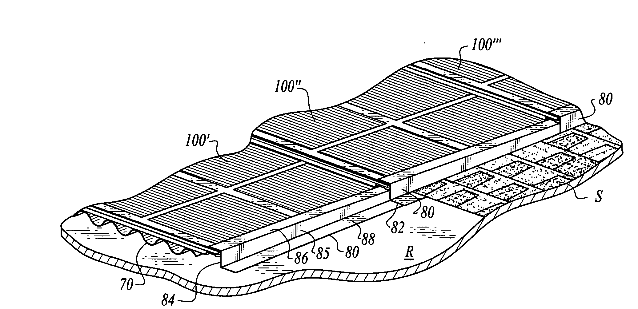
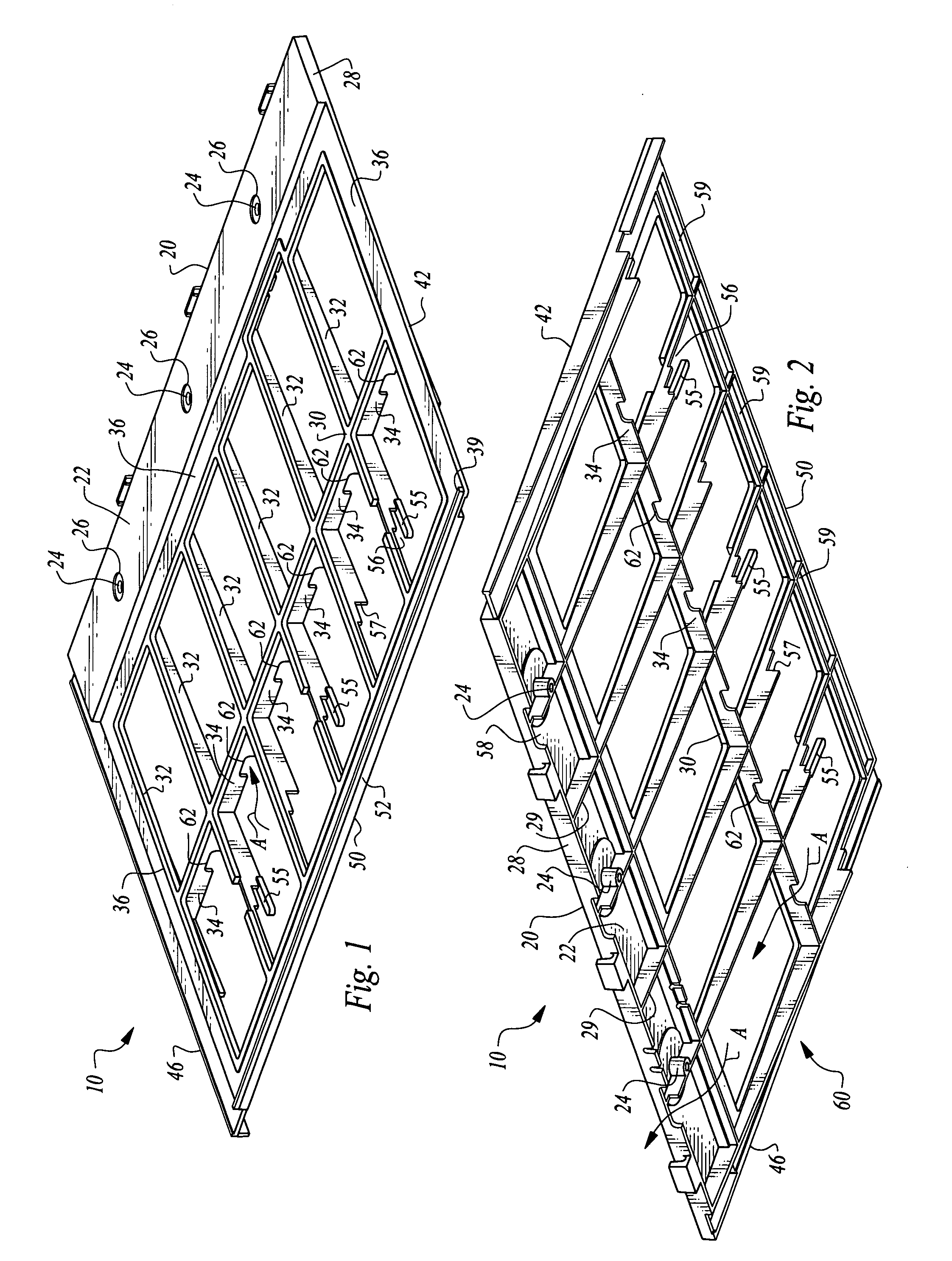
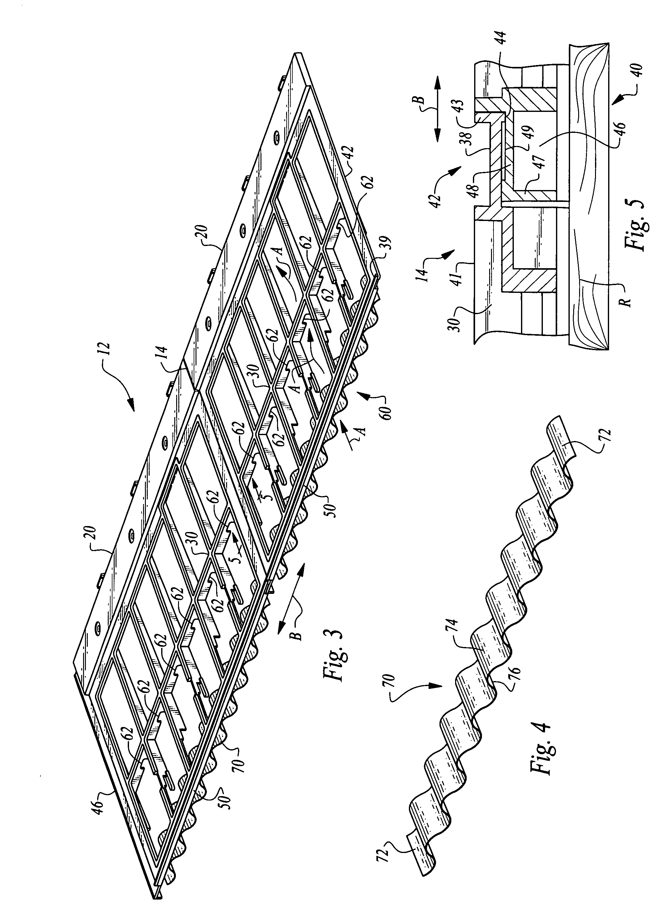
[0035]Referring to the drawings, wherein like reference numerals represent like parts throughout the various drawing figures, reference numeral 10 is directed to a bracket (FIGS. 1 and 2) for a roof mounted photovoltaic power generation system. The brackets 10 are provided in pairs 12 (FIG. 3) which together support a photovoltaic cell 102 stack assembly to form a panel 100 (FIG. 9). The panel 100 can act similar to a shingle S (FIG. 13) upon the roof R to shed water and protect structural portions of the roof. The brackets 10 interlock together laterally and vertically while accommodating airflow therebeneath for cooling. The brackets also accommodate thermal expansion and have edge details to facilitate airflow and to provide water preclusion. The brackets are also configured to facilitate interconnection of an electric subsystem 110 for combining adjacent panels 100 together as part of the overall photovoltaic power generation system.

[0036]In essence, and with particular referenc...


PUM


Abstract

Multiple brackets are used together to support photovoltaic cells upon a roof. Each bracket includes a mounting rail at an upper side and a bottom rail at a lower side. The bottom rail of one bracket is configured to overlap the mounting rail of another bracket. Lateral joints on each bracket overlap each other to connect adjacent panels of photovoltaic cells. Cell support structures are interposed between the mounting rail and bottom rail to support a photovoltaic stack assembly thereon. Wind clips allow the bottom rail of a higher bracket to be interconnected with a mounting rail of a lower bracket. An undulating end piece allows airflow to enter beneath a lowest bracket and pass up beneath the brackets to provide cooling air for the overall system of photovoltaic cells mounted upon the brackets. Edge flashing precludes water migration laterally at edges of the panels.

Description

FIELD OF THE INVENTION[0001]The following invention relates to mounting systems for mounting photovoltaic cells on roofs of buildings. More particularly, this invention relates to mounting brackets and mounting bracket systems which are particularly configured for supporting photovoltaic cells upon composition roofs in a manner which has a low profile and blends in nicely with adjacent shingles.BACKGROUND OF THE INVENTION[0002]Photovoltaic cells have enjoyed increasing popularity over time as various different technical hurdles associated with the use of photovoltaic cells have been overcome. Photovoltaic cells are generally solid state devices formed of various materials (often silicon) which generate electric current when exposed to photonic radiation, such as solar radiation.[0003]One form of photovoltaic cell is configured so that it can rest upon a bracket which is particularly configured to be mounted to the shingles on a roof or directly upon the roof and have perimeter edges...

Claims


Application Information

Patent Timeline
IPC IPC(8): E04D13/18E04B1/38F28D15/00
CPCY02B10/12Y02B10/20H02S20/25F24S25/00H02S20/23Y02E10/47Y02E10/50Y02B10/10
Inventor GANGEMI, RONALD J.
Owner GANGEMI RONALD J
Why Eureka
Try Eureka