This helps you quickly interpret patents by identifying the three key elements:
Problems solved by technology
Method used
Benefits of technology
Benefits of technology
[0015]The present invention realizes the following advantageous effects:[0016]1. The acoustic emission test sensor fixing device according to the present invention is convenient in use, and it can also attach the acoustic emission test sensors tightly to the tested member during the whole testing process and keep the end face of the acoustic emission test sensors mounted in the acoustic emission test sensor fixing device parallel to the coupling surface of the tested member, thereby ensuring the truthfulness of the testing result and improving the accuracy of the testing result.[0017]2. As the radial positioning mechanism comprises elastic members, when the tested member swells radially in the experiment, force of the acoustic emission test sensor will not increase, which could easily ensure force consistency of the acoustic emission test sensor during testing for the same batch of tested members, thereby lowering the influence of the pseudo signals on the test result and also improving the life of the acoustic emission test sensor.[0018]3. The acoustic emission test sensor fixing device according to the present invention makes it convenient to arrange the acoustic emission test sensor at any position on the surface of the tested member, where other deforming test sensors can be arranged at the same time, so as to obtain more different testing information of the tested member during the same testing process.[0019]4. Using the acoustic emission test sensor fixing device according to the present invention, the acoustic emission test sensor can be mounted at any period of time before or after pre-adding contact load to the tested member, and the position of the acoustic emission test sensor can also be adjusted during the experiment.
[0016]1. The acoustic emission test sensor fixing device according to the present invention is convenient in use, and it can also attach the acoustic emission test sensors tightly to the tested member during the whole testing process and keep the end face of the acoustic emission test sensors mounted in the acoustic emission test sensor fixing device parallel to the coupling surface of the tested member, thereby ensuring the truthfulness of the testing result and improving the accuracy of the testing result.
[0017]2. As the radial positioning mechanism comprises elastic members, when the tested member swells radially in the experiment, force of the acoustic emission test sensor will not increase, which could easily ensure force consistency of the acoustic emission test sensor during testing for the same batch of tested members, thereby lowering the influence of the pseudo signals on the test result and also improving the life of the acoustic emission test sensor.
[0018]3. The acoustic emission test sensor fixing device according to the present invention makes it convenient to arrange the acoustic emission test sensor at any position on the surface of the tested member, where other deforming test sensors can be arranged at the same time, so as to obtain more different testing information of the tested member during the same testing process.
[0019]4. Using the acoustic emission test sensor fixing device according to the present invention, the acoustic emission test sensor can be mounted at any period of time before or after pre-adding contact load to the tested member, and the position of the acoustic emission test sensor can also be adjusted during the experiment.
Problems solved by technology
Acoustic emission test sensors generally have a diameter within the range of 5 mm to 15 mm and need to couple tested members using media, such as gel, butter, vaseline and etc. as a coupler, which result in that the fixing methods of winding with rubber belt and fastening with bungee are unable to ensure parallelism between the end face of the acoustic emission testing sensor and the coupling face of the tested member and the fine coupling between the end face of the acoustic emission test sensor and the tested member.
Also, couplers such as butter, vaseline and etc, which may easily result in the adhesion reduction or failure of the rubber belt, and the rubber belt may easily form great binding on the acoustic emission test sensor during radial swelling and deforming of the tested member, so that it undertakes increasing force and is even damaged to some extent; for the fixing method of fastening by bungee, although the bungee is elongated by pulling during radial swelling and deforming of tested member and may deform to some extent, this fixing method may easily cause the acoustic emission test sensor to tumble, and thus it is difficult to ensure fine contact between the acoustic emission test sensor and the tested member.
In addition, the above mentioned two fixing methods need to be performed before test pre-adding contact load and adjustment cannot be made during the experiment, and it is also difficult to accurately contraposition the acoustic emission test sensor.
The above mentioned two fixing methods also have the following problems: (1) they can hardly ensure the consistency of force to the acoustic emission test sensor in the same batch of tested members and may easily form many pseudo signals, thus resulting in much difficulty to analysis and judgment of the testing result; and (2) they make the mounting of other deforming test sensors are very inconvenient.
Method used
Image
Click on the blue label to locate the original text in one second.
Reading with bidirectional positioning of images and text.
Examples
embodiment 1
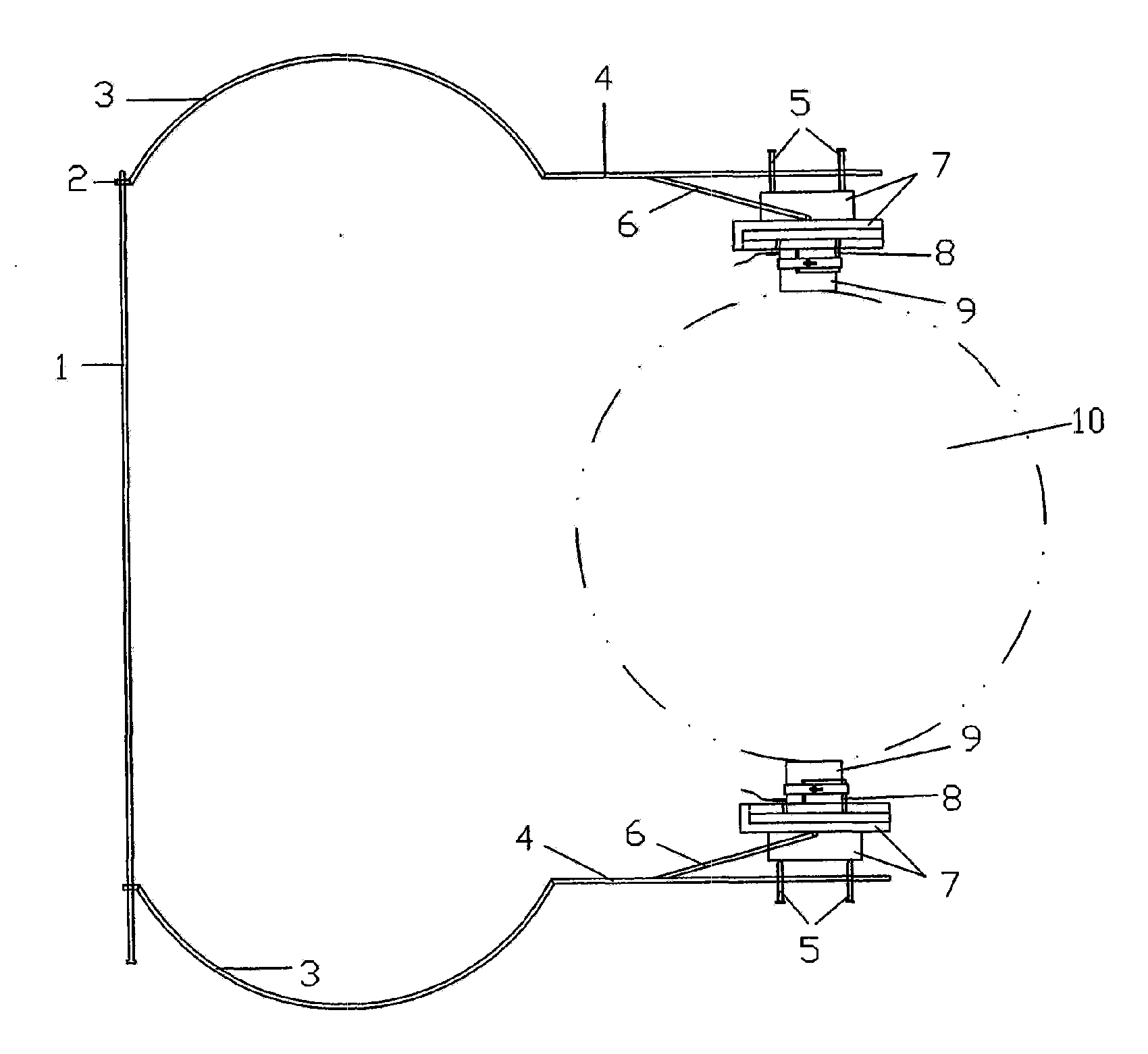
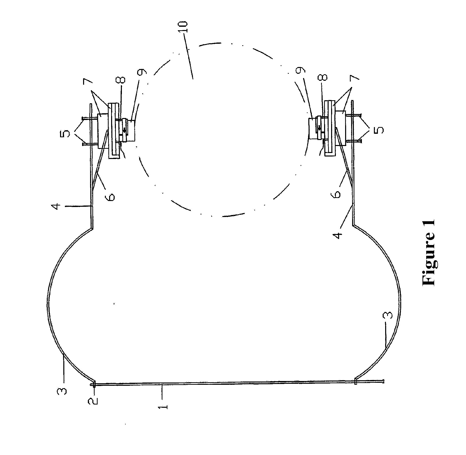
[0035]In this embodiment, the structure of the acoustic emission test sensor is shown in FIG. 1, which comprising radial positioning mechanism, supporting mechanisms, bases 7, acoustic emission test sensor mounting mechanisms 8, and parallelism adjusting members 5, wherein the supporting mechanisms, the bases, the acoustic emission test sensor mounting mechanisms, and the parallelism adjusting members are all in two sets.
[0036]The radial positioning mechanism, as shown in FIG. 1, comprises two arc elastomers 3 and one screw 1, and the two arc elastomers are respectively connected with rigid ends 2 at respective one end, each of said rigid ends is provided with a screw hole matching the screw, and the screw forms screw pairs with the screw holes in the two rigid ends. The supporting mechanism, as shown in FIG. 1, comprises main supporting arm 4 and auxiliary supporting arm 6; the main supporting arms 4 are made of nickeltitaniumalloy and has a rectangular cross section, and are pro...
embodiment 2
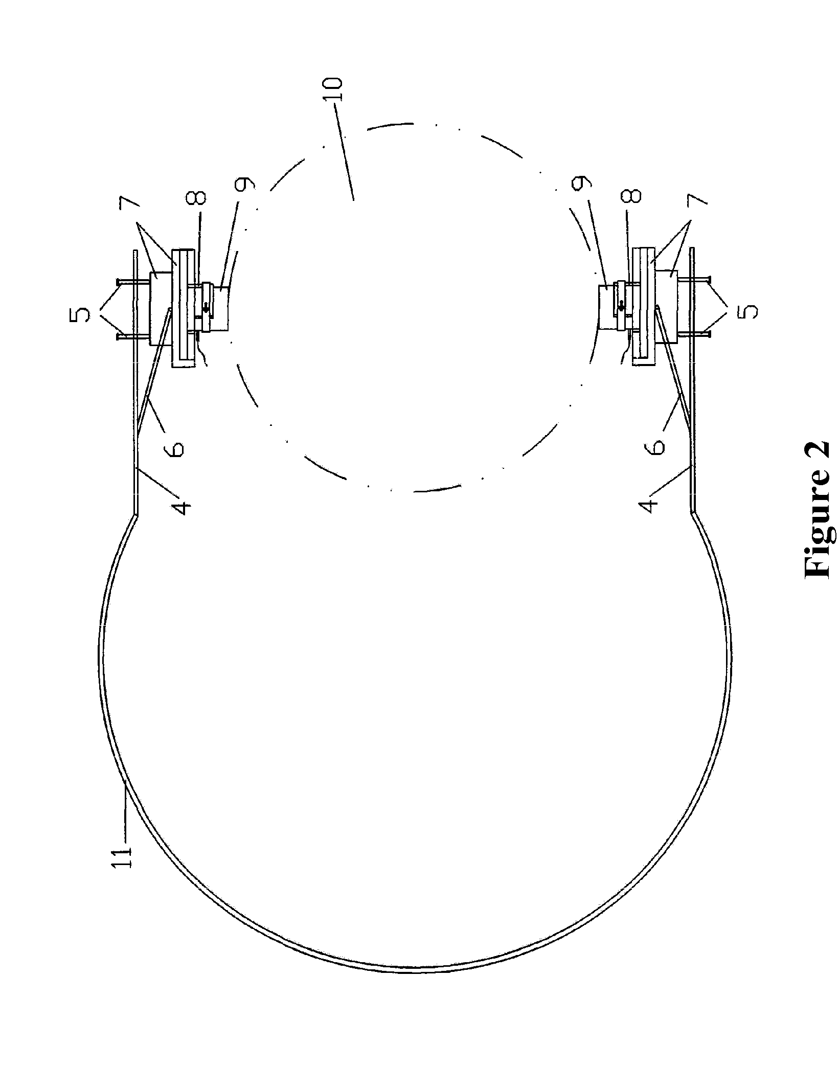
[0038]In this embodiment, the structure of the acoustic emission test sensor fixing device is shown in FIG. 2, comprising a radial positioning mechanism, supporting mechanisms, bases 7, acoustic emission test sensor mounting mechanisms 8, and parallelism adjusting members 5, wherein the supporting mechanisms, the bases, the acoustic emission test sensor mounting mechanisms, and the parallelism adjusting members are all in two sets.
[0039]Different from embodiment 1, it is described in embodiment 2 that 1) the radial positioning mechanism is a semicircular elastomer 11 (as shown in FIG. 2); and 2) the acoustic emission test sensor mounting mechanism 8 is shown in FIGS. 9 and 10, wherein the plugboard 16 is provided with a fixing buckle 21 thereon, and when the plugboard 16 is inserted into the slot 15 which is in the base, it is fixed by the fixing buckle 21; the circular elastic plate 18 provided with the gap is put around the gap section of the cylinder, and the acoustic emission te...
embodiment 3
[0040]In this embodiment, the structure of the acoustic emission test sensor fixing device is shown in FIG. 3, comprising a radial positioning mechanism, supporting mechanisms, bases 7, acoustic emission test sensor mounting mechanisms 8, and parallelism adjusting members 5, wherein the supporting mechanisms, the bases, the acoustic emission test sensor mounting mechanisms, and the parallelism adjusting members are all in two sets.
[0041]Different from embodiment 1, it is described in embodiment 3 that the auxiliary support arms 6 is in a “hook shape”, and is provided with a screw fixedly connected with the main supporting arm 4 or kink shafts hinged with the main support arm 4 at the upper end, and is provided with the kink shaft member 14 at the lower end (as shown in FIG. 3), when the auxiliary supporting arm is fixedly connected with the main supporting arm, the angle between auxiliary supporting arm and the main supporting arm is right angle (as shown in FIG. 3), and when the au...
PUM
Property
Measurement
Unit
Diameter
aaaaa
aaaaa
Abstract
An acoustic emission test sensor fixing device, comprising a radial positioning mechanism, supporting mechanisms, bases, acoustic emission test sensor mounting mechanisms, and parallelism adjusting members, wherein the supporting mechanism comprises a main supporting arm and an auxiliary supporting arm, with one end of the auxiliary supporting arm is fixedly connected to or hinged with the main supporting arm and the other end is provided with kink shaft members which are symmetrical about the auxiliary supporting arm; and the bases are provided with plugholes which form revolute pairs with the auxiliary supporting arm. The above components are assembled as follows: the main supporting arms of the two sets of supporting mechanisms are connected to the two free ends of the radial positioning mechanism respectively in the way that the auxiliary supporting arms of the two sets of supporting mechanisms are located at the inner sides of the main supporting arms respectively and are arranged axis symmetrically with respect to the central line of the radial positioning mechanism, and the kink shaft members of the two auxiliary supporting arms are respectively inserted into the plugholes of the two bases to form revolute pairs, the two sets of acoustic emission test sensor mounting mechanisms are respectively mounted at the two bases, and the two sets of parallelism adjusting members are respectively mounted on the two main supporting arms and correspond to the positions of the bases.
Description
FIELD OF THE INVENTION[0001]The present invention relates to an acoustic emission test sensor fixing device used in columnar test piece experiment and test of materials such as rock and concrete.BACKGROUND OF THE INVENTION[0002]In rock mechanical experiments, when acoustic emission features of rock damage process and etc. are tested, the acoustic emission test sensors currently used do not have specific fixing devices, and two fixing methods of winding with rubber belt and fastening with bungee are commonly adopted in current experiments and tests. Acoustic emission test sensors generally have a diameter within the range of 5 mm to 15 mm and need to couple tested members using media, such as gel, butter, vaseline and etc. as a coupler, which result in that the fixing methods of winding with rubber belt and fastening with bungee are unable to ensure parallelism between the end face of the acoustic emission testing sensor and the coupling face of the tested member and the fine couplin...
Claims
Application Information
Patent Timeline
Application Date:The date an application was filed.
Publication Date:The date a patent or application was officially published.
First Publication Date:The earliest publication date of a patent with the same application number.
Issue Date:Publication date of the patent grant document.
PCT Entry Date:The Entry date of PCT National Phase.
Estimated Expiry Date:The statutory expiry date of a patent right according to the Patent Law, and it is the longest term of protection that the patent right can achieve without the termination of the patent right due to other reasons(Term extension factor has been taken into account ).
Invalid Date:Actual expiry date is based on effective date or publication date of legal transaction data of invalid patent.

