Blade arrangement for disk harrows

a disk harrow and blade arrangement technology, applied in the field of tillage equipment, can solve the problems of increasing the overall weight of the implement, limiting the design of larger-size disk harrows, and creating maintenance challenges, so as to prevent or minimize the divergence of disk gangs. the effect of a larger width and disk harrows

Inactive Publication Date: 2010-12-16
HENNES MARK
View PDF61 Cites 19 Cited by
  • Summary
  • Abstract
  • Description
  • Claims
  • Application Information

AI Technical Summary

Benefits of technology

[0010]An object of the present invention is to provide a disk harrow design that prevents or minimi...

Problems solved by technology

Moreover, Elliott's disk harrow was a single section implement that was not designed to fold between a relatively wide position for fieldwork and a relatively narrow position for transport.
The conventional arrangement of diverging disk gangs has limited the design of larger size disk harrows, which are growing in demand for use with today's larger size tractors.
The conventional arrangement of disk gangs al...

Method used


Image

  • Blade arrangement for disk harrows
  • Blade arrangement for disk harrows
  • Blade arrangement for disk harrows

Examples


Embodiment Construction

[0037]A tandem disk harrow according to embodiments of the present invention will now be described in detail with reference to FIGS. 1 to 16 of the accompanying drawings.

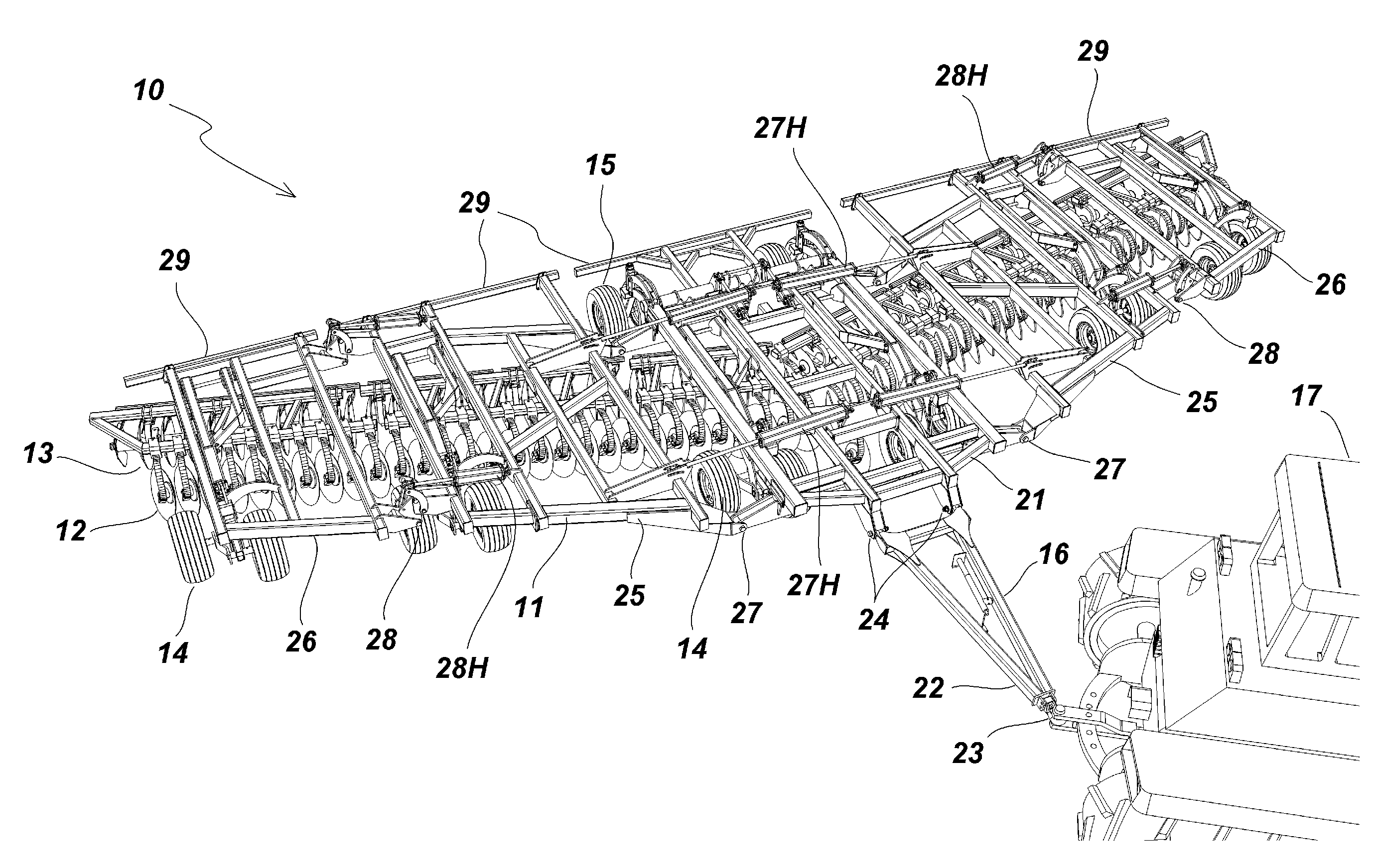
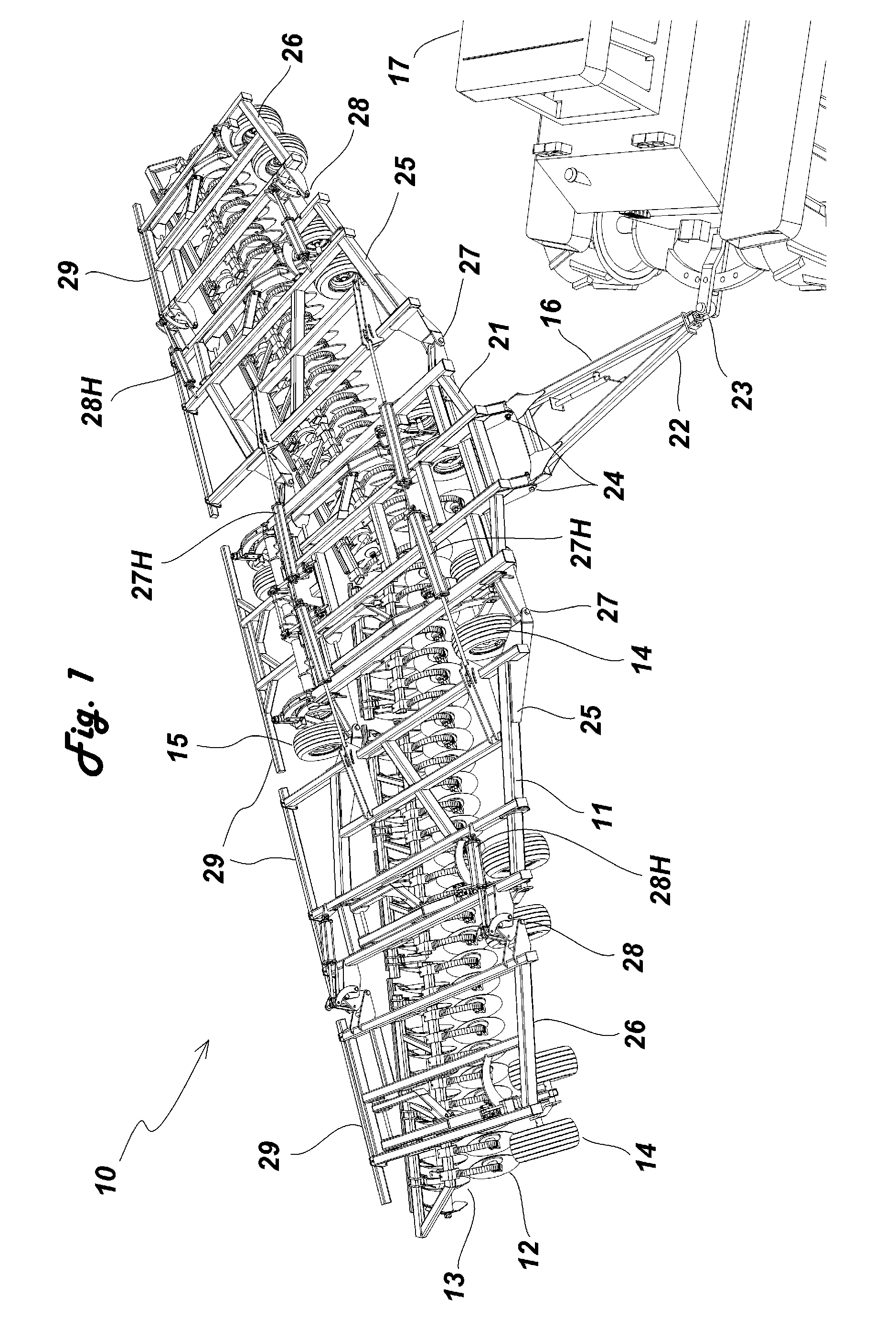
[0038]A five-section tandem disk harrow 10 according to the present invention is shown in FIG. 1. The disk harrow 10 has a frame 11, a front disk gang 12, a rear disk gang 13, a plurality of depth gauging wheels 14, 15, and a substantially free floating hitch assembly 16. The disk harrow 10 can be attached to a tractor 17 and used to provide either primary or secondary tillage of an agricultural field.

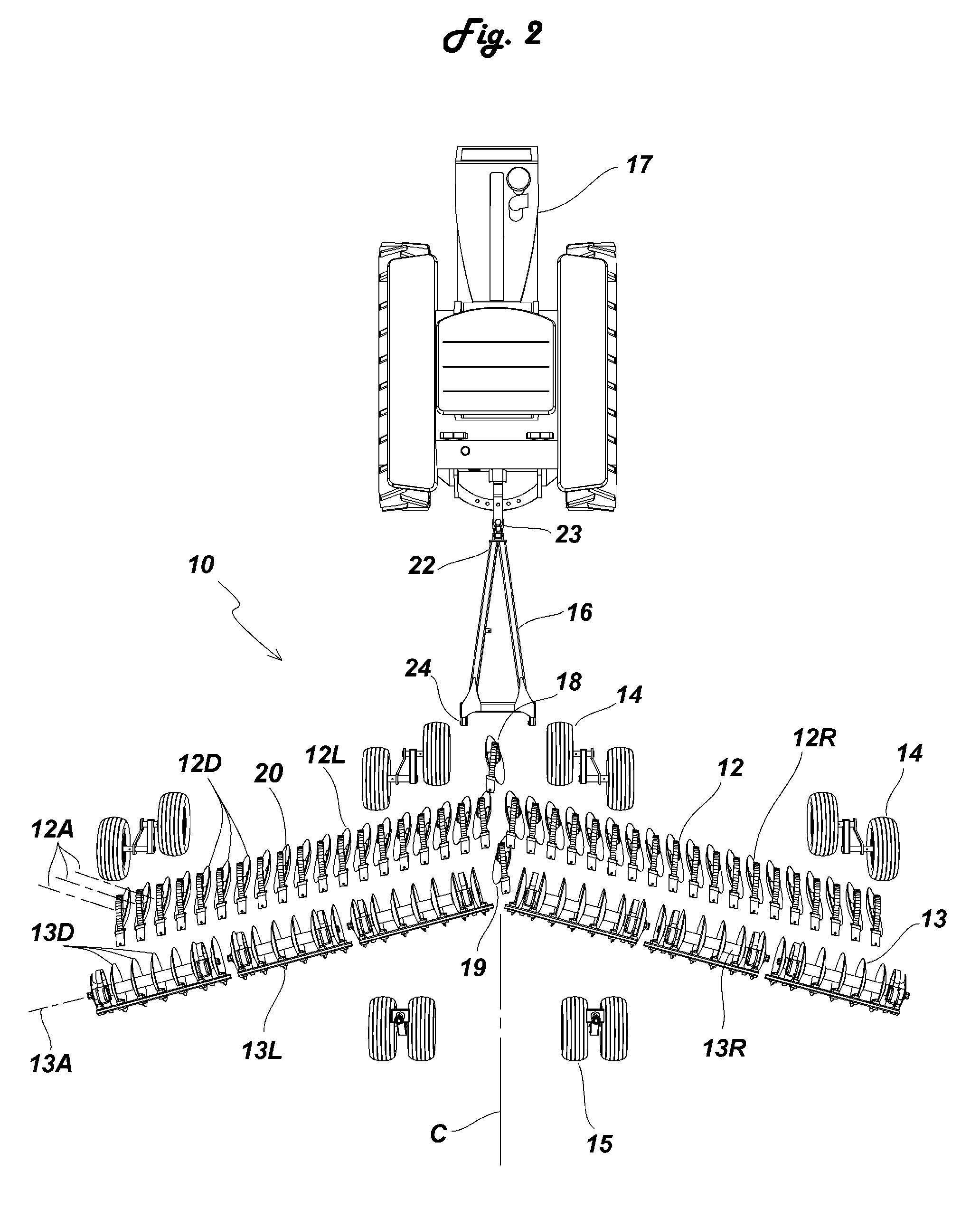
[0039]A portion of the disk harrow 10 is shown in plan view in FIG. 2. The frame 11 and outer wing sections of the disk harrow 10 have been omitted from FIG. 2 to provide a clearer illustration of the arrangement of the disk gangs 12, 13 and the depth gauging wheels 14, 15.

[0040]In FIG. 2, the front and rear disk gangs 12, 13 on each side of the longitudinal centerline C of the disk harrow 10 are substantially parallel...


PUM


Abstract

A multisection tandem disk harrow has a frame, a first disk gang, and a second disk gang. The concave sides of the disk blades in the first disk gang face one side of the disk harrow, and the concave sides of the disk blades in the second disk gang face the other side of the disk harrow. The disk blades in the first disk gang are mounted for rotation about a common axis that extends through a center of the disk blades. The disk blades in the second disk gang are mounted for rotation about respective individual axes that are substantially parallel with and spaced apart from each other. The first and second disk gangs are arranged so that the common axis of the first disk gang is nonparallel with the individual axes of the second disk gang. Various frame, support wheels, disk gang, and hitch configurations are also disclosed.

Description

BACKGROUND OF THE INVENTION[0001]1. Field of the Invention[0002]The present invention relates generally to tillage equipment, and in particular, to disk harrow implements having a front disk gang followed by a rear disk gang.[0003]2. Description of the Related Art[0004]Disk harrows are implements used to cultivate the surface of the soil. Disk harrows can be used to break up clods and lumps of soil, size and bury crop residue, and to provide a finer finish, a good tilth or soil structure that is suitable for seeding and planting operations. Disk harrows can also be used to remove weeds and to help level the surface of a rough field.[0005]Conventional disk harrows include gangs of disk blades supported for rotation by bearings mounted on hangers that extend downwardly from a frame. The disk gangs usually have a plurality of concave disks mounted for rotation on a common axis that extends at an angle to the direction of travel of the implement. Various arrangements of disk gangs are k...

Claims


Application Information

Patent Timeline
IPC IPC(8): A01B5/00A01B23/04A01B63/02A01B73/04
CPCA01B21/083A01B23/04A01B73/046
Inventor HENNES, MARK
Owner HENNES MARK
Why Eureka
Try Eureka