
Charging vehicle for an automatic assembly machine for photovoltaic modules

a photovoltaic module and charging vehicle technology, applied in the field of ground vehicles, to achieve the effect of reducing the wind load reducing the overall height of the ground vehicle, and reducing the overall height of the photovoltaic system

Inactive Publication Date: 2010-12-16
ADENSIS
View PDF12 Cites 8 Cited by
  • Summary
  • Abstract
  • Description
  • Claims
  • Application Information

AI Technical Summary

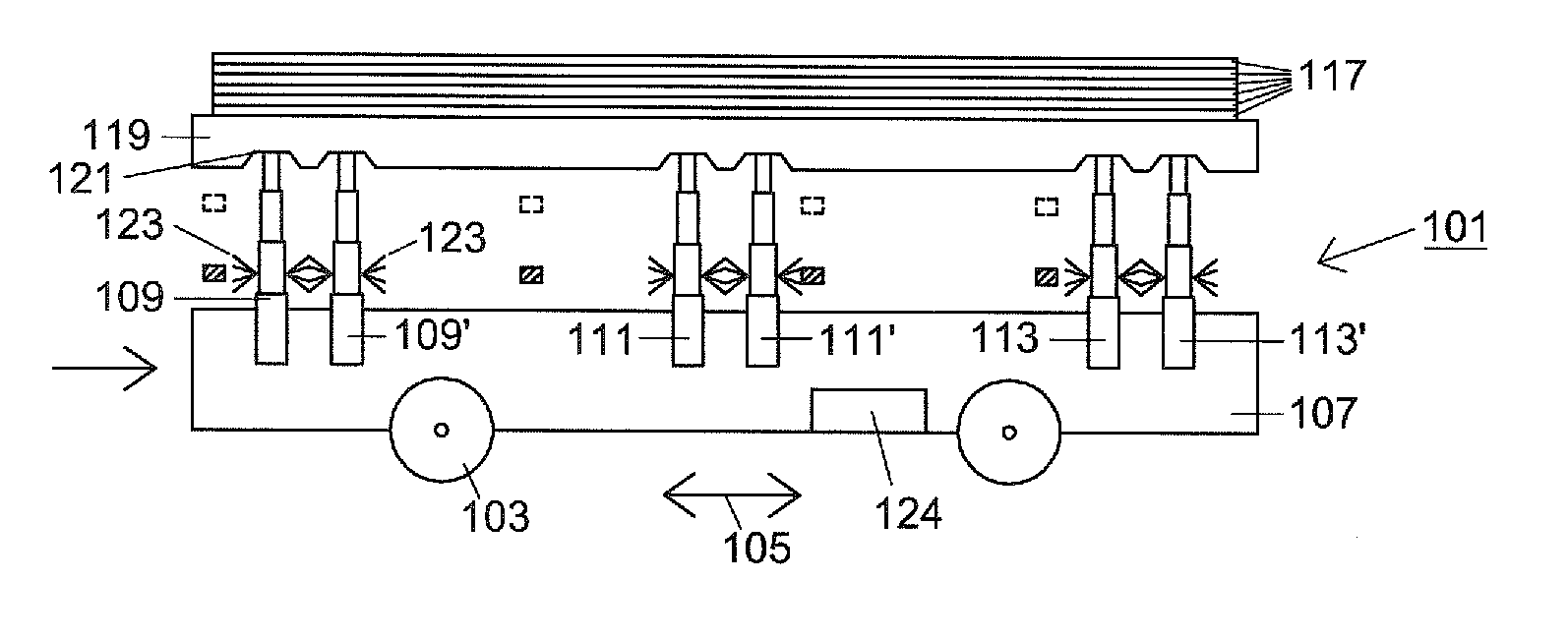
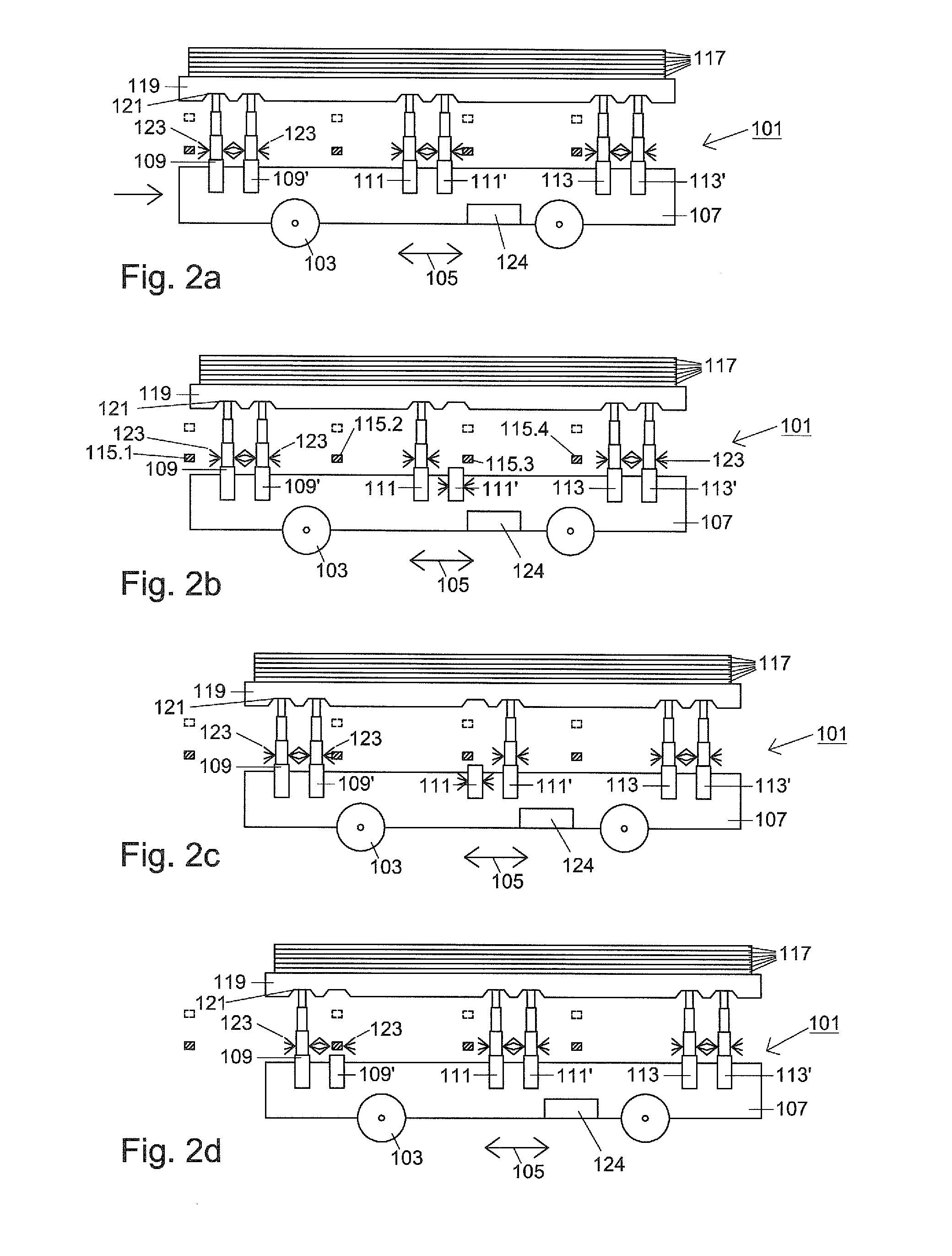
Benefits of technology

[0011]Advantageously, the rams may be extendable to a variable length, so that the support plate is maintained plane-parallel and at a predetermined distance from the area spanned by the transverse beams. This measure makes it possible to use short ram excursions, which reduces the time from actuation of the ram to the time when the ram reaches its end position.
[0012]Advantageously, after having traveled underneath a transverse beam, the ram disposed opposite to the travel direction (referred to above as the second ram or the counterpart) may be extended. During normal travel, both rams of a pair always provide support, which aids stability. Moreover, the travel is faster, because when the first ram approaches a transverse beam, this ram may be immediately lowered without having to wait for extension of the rear ram. The ground vehicle needs to stop only when the first ram has passed the transverse beam and the load is transferred (by extension of the first ram that has already passed, and lowering the counterpart ram to prepare for its crossing underneath).
[0013]If three or four ram pairs are more advantageous also depends on the geometry of the system. When using three ram pairs, the control is significantly less complex, but the steps for travel require more time, because the ground vehicle must stop again at the center ram pair. This disadvantage is eliminated when the four ram pairs engage on the ends of the system. On the other hand, three ram pairs may be provided, depending on the shape of the PV modules, in particular their length / width ratio, wherein one of the ram pairs is located on the edge midway between two corners, whereas the two other ram pairs are located at the corners of the opposite edge. This alternative embodiment may be tested first, because relatively large displacement steps are feasible with little control complexity.
[0016]According to another advantageous embodiment, the indentations may be funnel-shaped and the ends of the ram may be shaped as a truncated cone. This provides sufficient tolerance that the ram hits the notch during extension of the ram. At least one of the parts, ram or protrusion, may be made of an elastic material, such as hard rubber. A mixed shape of a notch made of Teflon and a ram end made of rubber is also feasible.
[0018]A particular advantage is the low overall height of the ground vehicle, which advantageously may be no higher than 0.5 m to 1.0 m when the rams are retracted. The overall height of the photovoltaic system should be kept as low as possible to reduce wind loading of the photovoltaic system. However, a practical installation requires an acceptable overall height. A low automated ground vehicle, which supports the installation from below, makes it possible to further lower the overall height, without loss of installation comfort.

Problems solved by technology

At this time, the individual photovoltaic modules must be conveyed to the automatic assembly machine by hand, which is expensive when considering the large number of several thousands of PV modules to be installed.

Method used


Image

  • Charging vehicle for an automatic assembly machine for photovoltaic modules
  • Charging vehicle for an automatic assembly machine for photovoltaic modules
  • Charging vehicle for an automatic assembly machine for photovoltaic modules

Examples


Embodiment Construction

[0026]Throughout all the figures, same or corresponding elements may generally be indicated by same reference numerals. These depicted embodiments are to be understood as illustrative of the invention and not as limiting in any way. It should also be understood that the figures are not necessarily to scale and that the embodiments are sometimes illustrated by graphic symbols, phantom lines, diagrammatic representations and fragmentary views. In certain instances, details which are not necessary for an understanding of the present invention or which render other details difficult to perceive may have been omitted.

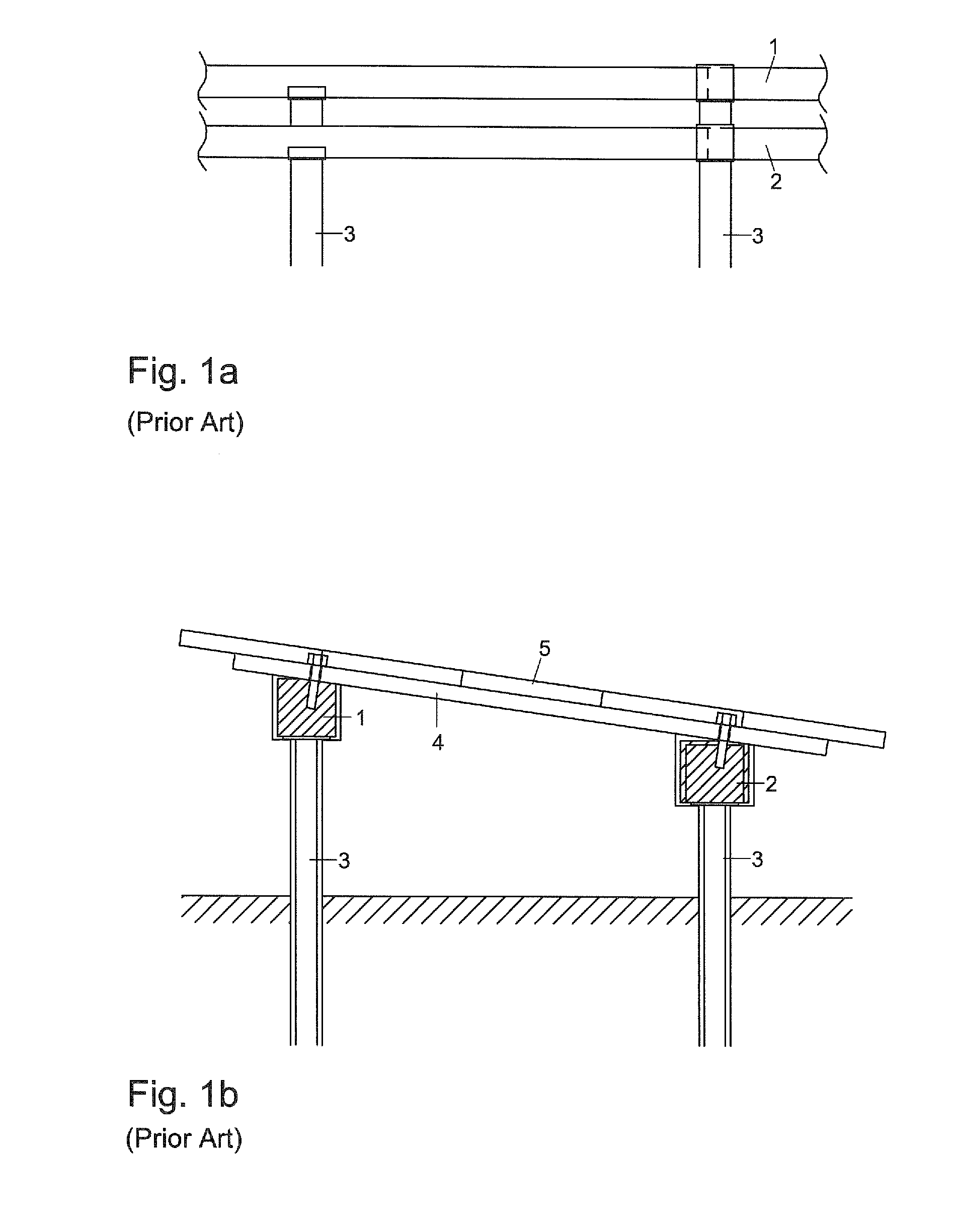
[0027]Turning now to the drawing, and in particular to FIGS. 1a and 1b, there are shown two rails or beams 1, 2 which are positioned at slightly different heights. The rails 1, 2 are attached to ground supports 3 which have different lengths commensurate with the different heights of the beams 1, 2. The ground supports are either pile-driven directly into the ground or conne...


PUM


Abstract

A ground vehicle for feeding photovoltaic modules to an automatic assembly machine is disclosed, wherein the automatic assembly machine is movable on previously installed PV modules and the PV modules that still need to be installed are fed to the automatic assembly machine above a supporting structure. The ground vehicle has six vertically movable rams arranged in spaced-apart relationship in pairs in the direction of travel, with the PV modules to be installed located above the rams. Timing of the vertical ram motion is controlled so that a retracted ram of a ram pair is always extended before the other ram of the ram pair is lowered.

Description

CROSS-REFERENCES TO RELATED APPLICATIONS[0001]This application claims the priority of German Patent Application, Serial No. 10 2009 024 740.8, filed Jun. 12, 2009, pursuant to 35 U.S.C. 119(a)-(d), the content of which is incorporated herein by reference in its entirety as if fully set forth herein.BACKGROUND OF THE INVENTION[0002]The present invention relates to a ground vehicle for transporting an article above an obstacle extending transversely to the travel direction. The ground vehicle is used to charge an automatic assembly machine with photovoltaic (PV) modules, wherein the automatic assembly machine is movable on previously installed photovoltaic modules and the photovoltaic modules that still need to be installed are presented to the automatic assembly machine above a loadbearing structure adapted to receive the photovoltaic modules. The ground vehicle may also be used for other purposes aside from the aforementioned use. For example, articles of any kind, as well as person...

Claims


Application Information

Patent Timeline
Patent Type & Authority Applications(United States)
IPC IPC(8): B60P1/02
CPCH01L21/67724H01L21/6773H01L31/02F24S25/12H02S20/10F24S2025/014Y02E10/47Y02E10/50
Inventor BECK, BERNHARD
Owner ADENSIS
Learn More