Floor covering and inductive power system

a technology of inductive power system and floor covering, which is applied in the direction of inductance, transformer, transportation and packaging, etc., can solve the problems of damage or destruction, interference with biological systems and implants, and harmful interactions with other electric and biological systems

Inactive Publication Date: 2010-12-16
KONINKLIJKE PHILIPS ELECTRONICS NV
View PDF7 Cites 280 Cited by
  • Summary
  • Abstract
  • Description
  • Claims
  • Application Information

AI Technical Summary

Benefits of technology

[0018]In one embodiment, the floor covering further comprises a magnetic material which is capable of improving the magnetic coupling between the coils and the power receiver circuit. Such a magnetic material may be soft-magnetic wires, a ferrite polymer compound or a mumetal foil.
[0019]A further embodiment of the floor covering comprises a visual indicator. This indicator is printed on the rear side of the floor covering. In a first refinement of this embodiment, the indicator indicates areas for cutting the floor covering. The indicator indicates where to cut the material best without cutting wires of the coils or wiring system. In a second refinement of this embodiment, the indicator indicates a predetermined point of fracture. Breaking at this predetermined point of fracture disconnects parts of the coils. In this case, the indicator indicates parts of coils that have to be cut when tailoring the floor covering to the exact room dimensions. This will prevent short-circuiting.
[0024]In a further refinement of the invention, the wiring is connected to each coil so as to supply the charging current to each coil selectively. The charging current is switched only to a coil of the plurality of coils with one or more power receiver circuits. In a further refinement of the invention, the charging current of two, e.g. adjacent, coils differs in phase or frequency so as to reduce unwanted steady-state superposition.

Problems solved by technology

In particular, conventional inductive power pads emit strong inductive fields which can interfere and produce harmful interactions with other electric and biological systems in close proximity.
These fields can produce eddy currents in unprotected electronics and consequently damage or destroy them, and they can interfere with biological systems and implants.

Method used


Image

  • Floor covering and inductive power system
  • Floor covering and inductive power system
  • Floor covering and inductive power system

Examples


Embodiment Construction

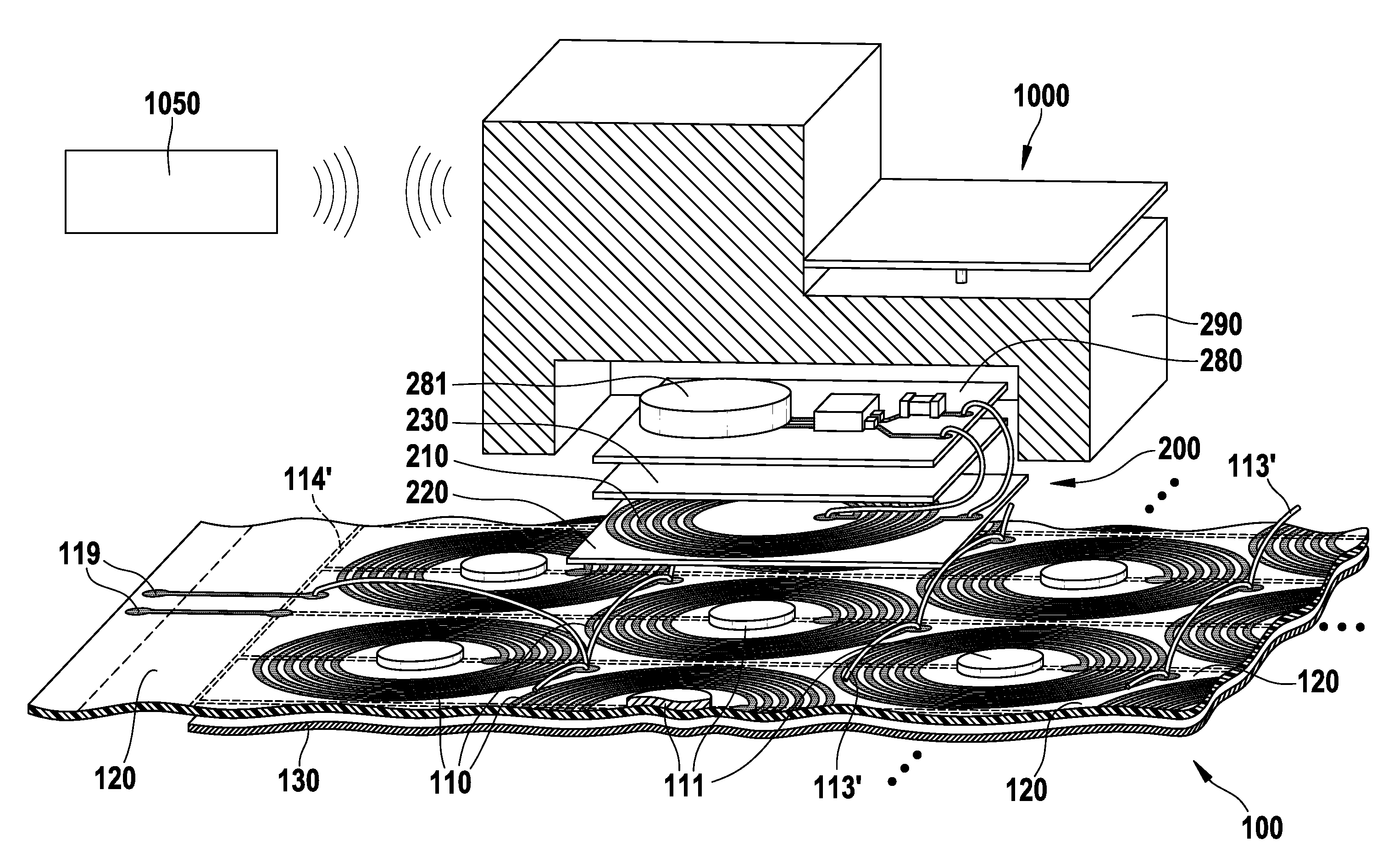
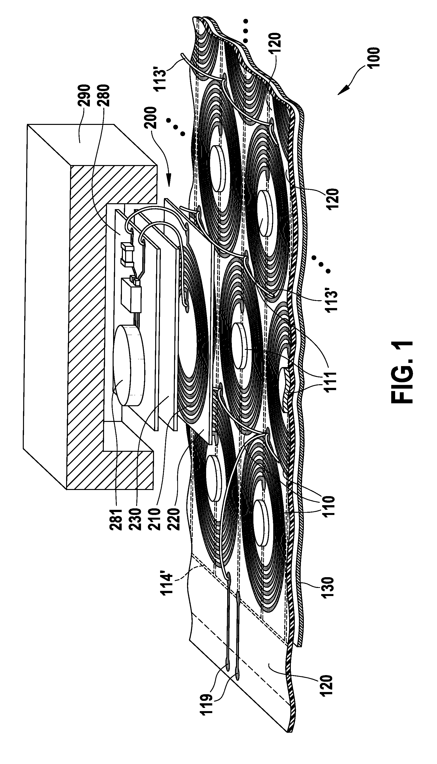
[0031]FIG. 1 is a schematic view of an inductive power system according to the invention. An electronic device as a power receiver circuit 200 is movable across a floor covering 100 used, for example, in an office room. The inductive power system generally includes the floor covering 100, a power supply (not shown), which is connected to the floor covering 100 by a connecting part 119 of the floor covering 100, and the power receiver circuit 200. The floor covering 100 comprises a plurality of coils 110 which are operable to supply inductive energy and operates as a base from which a portable appliance accommodating the power receiver circuit 200 with a rechargeable battery 281 is charged.

[0032]For example, the floor covering 100 may be a flat, wooden base with the plurality of coils on its rear side onto which the portable appliances, e.g. vacuum cleaners, office tables with additional electronic equipment, lamps, thermostats, foot switches, robots, loudspeakers, furniture with int...


PUM


Abstract

The invention relates to a floor covering (100) comprising: a plurality of coils (110), each coil (110) being operable to supply inductive energy to a power receiver circuit (200); wherein the plurality of coils comprises a transmitter area occupying the largest area of the floor covering (100); and a charging current through the coils is operable to generate said inductive energy.

Description

FIELD OF THE INVENTION[0001]The present invention relates to inductive power systems and a floor covering, and more particularly to a floor covering comprising one or more coils of the inductive power system which is operable to supply inductive energy to a power receiver circuit.BACKGROUND OF THE INVENTION[0002]A large percentage of present-day electronics operates wirelessly, and this trend is expected to increase in the future. Portable appliances such as cell-phones, PDA, remote controls, notebooks, lamps, etc. represent only the beginning of what is expected to be a growing number of wireless devices in various industrial sectors.[0003]Portable and wireless appliances typically require power for operation, usually coming in the form of portable power storage by rechargeable or replaceable batteries. Rechargeable batteries are particularly advantageous, as they avoid the necessity of frequent replacement. Rechargeable batteries are often recharged by using induction means, where...

Claims


Application Information

Patent Timeline
Patent Type & Authority Applications(United States)
IPC IPC(8): H02J17/00E04B5/43H02J7/00
CPCH02J5/005H02J7/025H02J50/12H01F38/14H02J13/00H02J7/0042H02J50/402H02J50/005H02J50/90
Inventor BUDDE, WOLFGANG OTTOSNIJDER, PIETER JACOBVAN DER POEL, LUCAS LEO DISIREETEEVEN, VICTOR ADRIANUS JOSEPHWAFFENSCHMIDT, EBERHARD
Owner KONINKLIJKE PHILIPS ELECTRONICS NV
Why Eureka
Try Eureka