Spark plug

a spark plug and plug-in technology, applied in the field of spark plugs, can solve the problems of small diameter and decrease in the frequency of discharge at the normal spark gap, and achieve the effect of reducing the diameter of the spark plug, ensuring the ignition performance, and ensuring the strength of the plug

Active Publication Date: 2010-12-16
NGK SPARK PLUG CO LTD
View PDF8 Cites 12 Cited by
  • Summary
  • Abstract
  • Description
  • Claims
  • Application Information

AI Technical Summary

Benefits of technology

[0012]According to this form, since the gap between the insulating member and the metal shell and the dimension of the spark gap can be set to an optimal ratio, even with the spark plug with the small diameter, an igniting performance equal to or better than that of a spark plug with the standard diameter can be ensured. Further, according to the ratio, even in the event that the diameter of the spark plug is reduced, the thicknesses of the metal shell and the ground electrode do not have to be thinned more than required. Because of this, even in the event that the diameter of the spark plug is decreased, the strength thereof can be ensured.
[0013]In the spark plug of the above aspect, a dimension of the spark gap may be 0.6 mm or larger and 1.2 mm or smaller. According to this form, a sufficient gap can be ensured between the front end portion of the insulating member and the front end portion of the metal shell while ensuring the ignition performance.
[0014]In

Problems solved by technology

However, with these required countermeasures implemented, since a space where to install spark plugs, which are to be install in the internal combustion engine, becomes small, spark plugs with smaller

Method used


Image

  • Spark plug
  • Spark plug
  • Spark plug

Examples


first example

C-1 First Example

[0072]In a first example, the reason that the projecting amount H is referred to as 2 mm or larger will be described. Firstly, in this first example, a plurality of samples of spark plugs 100 were prepared which had different projecting amounts H by which the front end of the insulator 10 projects and volumes Vc. Specifically, samples were prepared whose volumes were 5, 8, 11, 12 and 13 mm3, and projecting amounts H of their insulators 10 were adjusted from −0.5 mm to 3.0 mm in 0.5 mm increments, whereby a total of 40 different types of samples was prepared.

[0073]In this example, front ends of the insulators 10 of these samples were heated by a burner, and time was measured which was spent until the temperature of the front ends of the insulator 10 had reached 500° C. since the start of the heating. The temperature of 500° C. is a temperature at which carbon sticking to the vicinity of the front ends of the insulators 10 start to be burned off.

[0074]FIG. 5 is a grap...

second example

C-2 Second Example

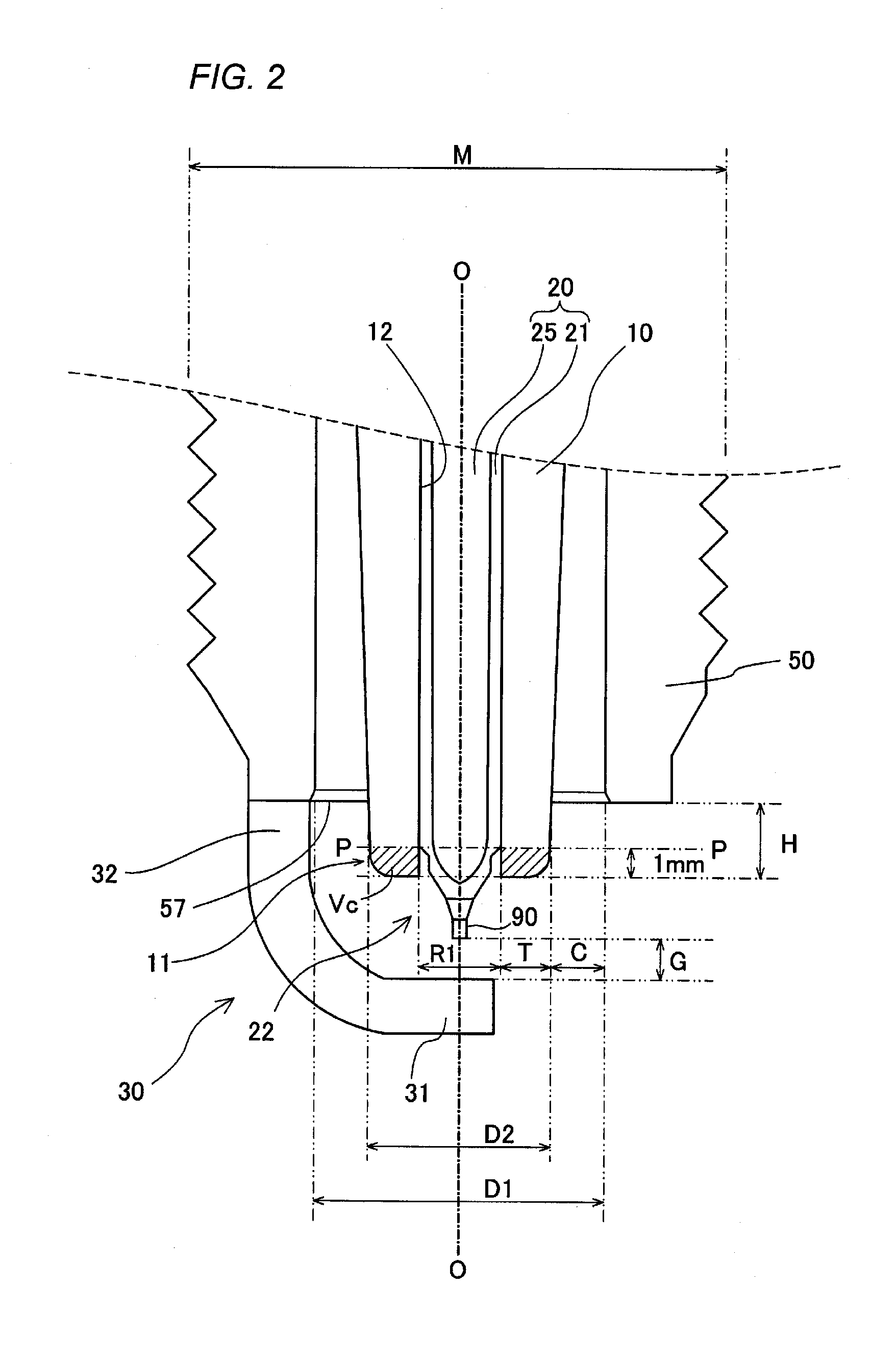
[0076]In a second example, the reason that the volume of the front end portion of the insulator 10 is referred to as 11 mm3 or smaller and the reason that the clearance C and the spark gap G are specified so as to satisfy the relation (1) will be described. In this second example, firstly, samples of spark plugs 100 were prepared in which diameters D1 (refer to FIG. 2) of holes in front ends of metal shells 50, outside diameters D2 (refer to FIG. 2) of front ends of insulators 10, clearances C (refer to FIG. 2) and spark gaps G (refer to FIG. 2) were varied variously.

[0077]FIG. 6 is a table showing part of dimensions of the samples prepared in this example. As is shown in the table, in the samples prepared in this example, although the hole diameters D1 of the metal shells 50 were all 6 mm, the outside diameters D2 of the insulators 10 were caused to vary from 3.3 mm to 5.2 mm, the clearances C from 0.4 mm to 1.35 mm, and the gaps from 0.6 mm to 1.1 mm. Ratios of c...

third example

C-3 Third Example

[0081]In a third example, the reason that the thickness T of the insulator 10 is specified to 0.7 mm or larger will be described. According to various experiments carried out by the applicant, it has been able to be verified that when the insulator was fouled with carbon, many lateral sparks occurred, whereas when the insulator was not so fouled, many inside sparks occurred. Then, in this third example, the following experiment was carried out to mainly suppress the occurrence of inside spark.

[0082]Namely, an experiment was carried out to study about a spark gap which triggers a inside spark by preparing samples in which thicknesses T of front end portions of insulators 10 were caused to vary in many ways, and adjusting dimensions of spark gaps of the samples so prepared. In this example, spark discharge was made 100 times for each spark gap, and when an inside spark occurred even once, it was judged that an inside spark was triggered with the spark gap. Namely, it ...


PUM


Abstract

A spark plug is such that a front end portion of an insulating member projects 2 mm or larger from a front end face of a metal shell and a volume of a portion of the insulating member which lies within a range from a front end of the insulating member to a position lying 1 mm towards a rear end side from the front end is 11 mm3 or smaller. When assuming that a corner portion where a front end face of the insulating member intersects a side surface of an axial hole is referred to as a position PA, a position on a center electrode where a straight-line distance from the position PA to the center electrode within the axial hole is referred to as a position PB, a position where the insulating member first contacts the metal shell from the front end face of the insulating element along a surface of the insulating element is referred to as a position PC, and a position on the insulating element where a straight line BC which connects the position PB with the position PC contacts the surface of the insulating member when the straight line BC is displaced parallel towards an outside of an axis is referred to as a position PD, a parallel displacement amount E by which the straight line BC is displaced parallel until it contacts the position PD is 0.75 mm or larger. According to the spark plug configured in this way, even though the spark plug is shaped small, the occurrence of lateral spark and inside spark can be suppressed effectively.

Description

TECHNICAL FIELD[0001]The present invention relates to a spark plug built in an internal combustion engine for igniting a fuel mixture.BACKGROUND ART[0002]Conventionally, in an internal combustion engine, spark plugs are used to ignite fuel mixtures. As is shown in FIG. 21, a general spark plug includes a center electrode, an insulating member which holds the center electrode in an axial hole, a metal shell which surrounds the periphery of the insulating member to hold the insulating member, and a ground electrode which is joined to the metal shell at a proximal end portion and which forms a spark gap at a distal end portion with the center electrode. The fuel mixture is ignited by a spark discharge occurring in the spark gap. Although the form of the spark plug shown in FIG. 21 is of a so-called projecting type, in addition to this, there are spark plugs of a slant type and a semi-creeping type (refer to JP-A-6-176849).[0003]In recent years, valve diameters of intake valves and exha...

Claims


Application Information

Patent Timeline
IPC IPC(8): H01T13/20
CPCH01T13/20H01T13/38
Inventor KYUNO, JIROSUZUKI, AKIRABAN, KENJI
Owner NGK SPARK PLUG CO LTD
Why Eureka
Try Eureka