Battery charging pad employing magnetic induction

a charging pad and magnetic induction technology, applied in the direction of inductance, transformer, transportation and packaging, etc., can solve the problems of troublesome setting the device on the charging pad, reduced power transmission efficiency, and difficulty in ensuring that all users are satisfied, and achieves simple circuit structure, rapid detection, and additional accuracy

Inactive Publication Date: 2010-12-16
SANYO ELECTRIC CO LTD
View PDF5 Cites 86 Cited by
  • Summary
  • Abstract
  • Description
  • Claims
  • Application Information

AI Technical Summary

Benefits of technology

[0016]In the battery charging pad of the present invention, the interval (d) between adjacent X-axis detection coils 30A can be smaller than the outside diameter (D) of the receiving coil 51 and smaller than the outside diameter (W) of the transmitting coil 11. Further, the interval (d) between adjacent Y-axis detection coils 30B can be smaller than the outside diameter (D) of the receiving coil 51 and smaller than the outside diameter (W) of the transmitting coil 11. This battery charging pad can detect receiving coil and transmitting coil position with additional accuracy.
[0017]In the battery charging pad of the present invention, a switching circuit 41 can be provided between the transmitting coil 11 and AC power source 12, and this switching circuit 41 can connect the transmitting coil 11 to the AC power source 12 to supply AC power to the transmitting coil 11 from the AC power source 12. Further, the switching circuit 41 can put both sides of the output at ground potential to allow detection of the transmitting coil 11 position. This battery charging pad can use the switching circuit that supplies AC power to the transmitting coil to control conditions for transmitting coil position detection. Consequently, provision of special purpose circuitry to put the transmitting coil in a state for position detection is unnecessary, and the transmitting coil position can be detected with a simple circuit structure.
[0018]In the battery charging pad of the present invention, a capacitor 18 connected in parallel with the transmitting coil 11 can be provided to form a parallel resonant circuit 19A. The capacitance C1 of the capacitor 18 connected in parallel with the transmitting coil 11 can be larger than the capacitance C2 of the capacitor 53 connected in parallel with the receiving coil 51 to form a parallel resonant circuit 54 in the device housing a battery 50. Thi

Problems solved by technology

This is because if there is offset in the position of the transmitting coil relative to the receiving coil, the coils cannot magnetically couple in an ideal manner, and power transmission efficiency is reduced.
Consequently, this system has the drawback that the device housing a battery cannot be set in an arbitrary position on the charging pad, and setting the device on the charging pad is troublesome.
It also has the drawback that it is difficult to insure that all the users will always properly set the device housing a battery on the charging pad.
Further, since this structure establishes

Method used


Image

  • Battery charging pad employing magnetic induction
  • Battery charging pad employing magnetic induction
  • Battery charging pad employing magnetic induction

Examples


Embodiment Construction

)

[0039]The following describes embodiments of the present invention based on the figures. However, the following embodiments are merely specific examples of battery charging pads representative of the technology associated with the present invention, and the battery charging pad of the present invention is not limited to the embodiments described below.

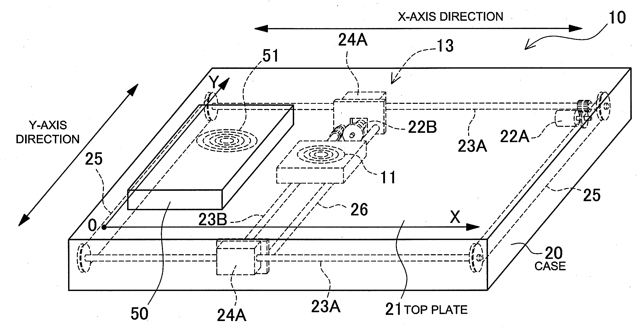
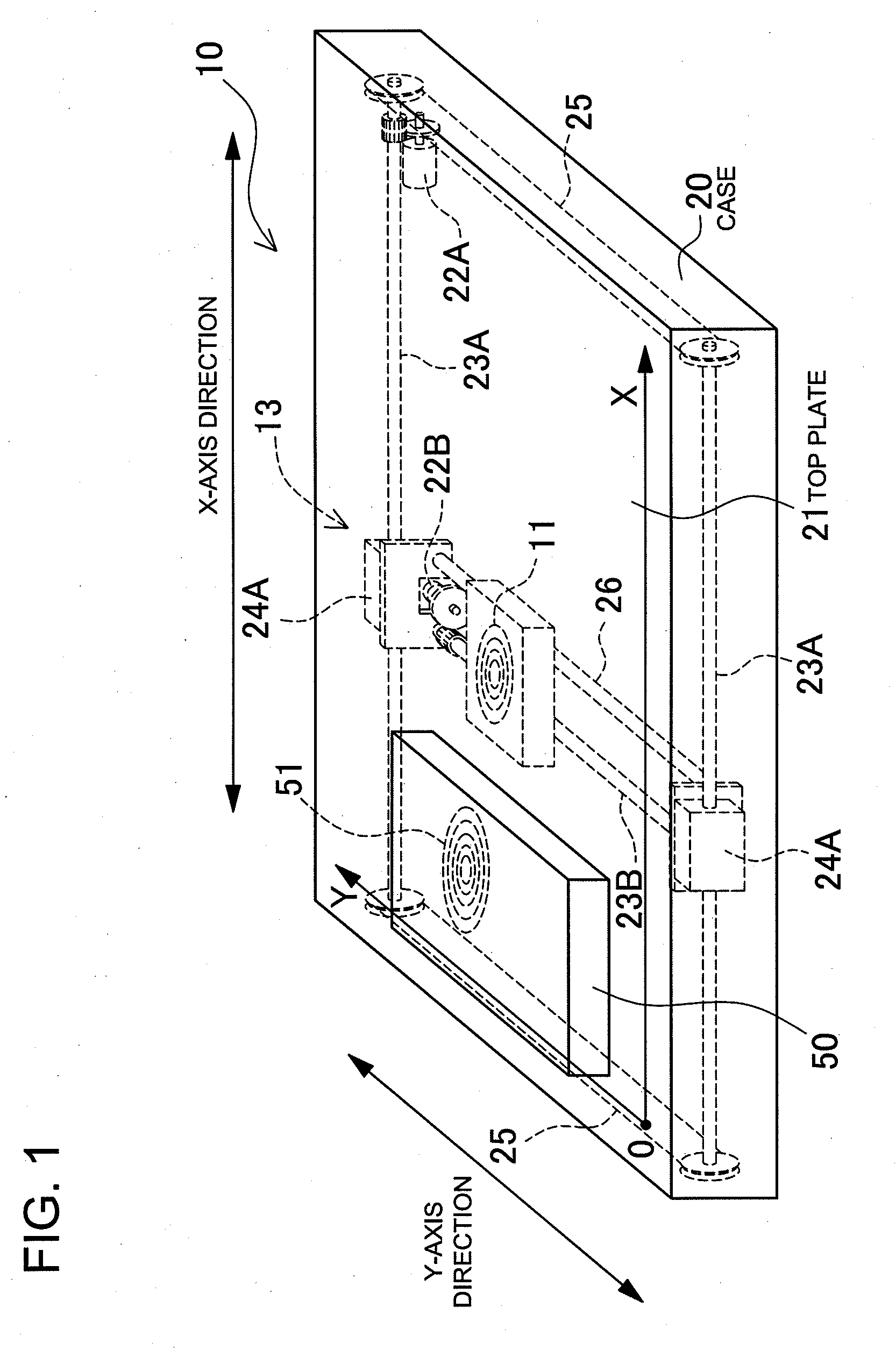
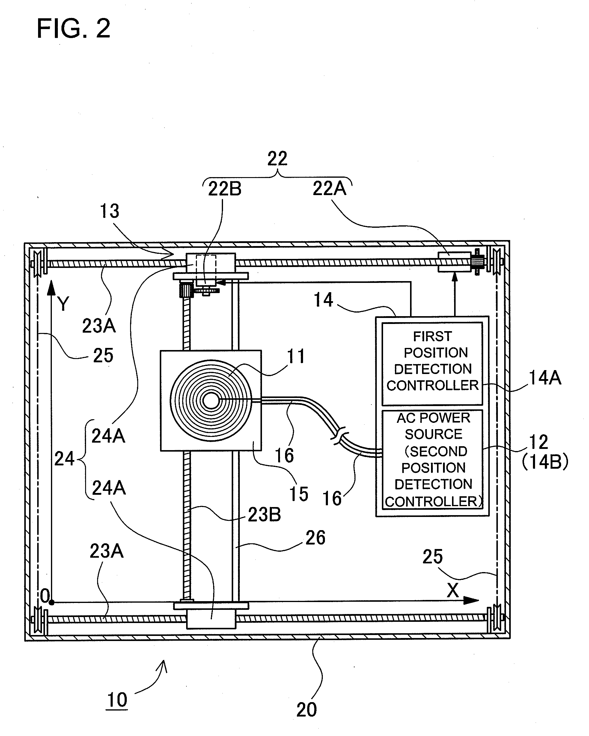
[0040]FIGS. 1-6 show abbreviated structural and conceptual views of a battery charging pad. As shown in FIGS. 1 and 6, a device housing a battery 50 is placed on the battery charging pad 10, and the internal battery 52 is charged utilizing magnetic induction. A device housing a battery 50 contains a receiving coil 51 that magnetically couples with the transmitting coil 11. The device housing a battery 50 also contains a battery 52 that is charged by power induced in the receiving coil 51. Here, the device housing a battery 50 can also be a battery pack.

[0041]FIG. 6 shows a circuit diagram of the device housing a battery 50. The device...


PUM


Abstract

The battery charging pad comprises a moving mechanism 13 that moves the transmitting coil 11, and a position detection controller 14 that detects the position of a device housing a battery 50 and controls the moving mechanism to move the transmitting coil in close proximity to a receiving coil 51. Pulse signals are supplied to a plurality of position detection coils 30 from a pulse generator 31, and the echo signals are a result of coil excitation by the pulse signals. The battery charging pad position detection controller 14 detects the position of the receiving coil 51 and moves the transmitting coil 11 in close proximity to the receiving coil 51, and the position detection controller 14 detects the position of the transmitting coil 11 and moves the transmitting coil 11 to the reference position, or it moves the transmitting coil 11 in close proximity to the receiving coil 51.

Description

BACKGROUND OF THE INVENTION[0001]1. Field of the Invention[0002]The present invention relates to a battery charging pad that transmits power by magnetic induction to charge rechargeable batteries contained in a device housing a battery that is placed on the charging pad.[0003]2. Description of the Related Art[0004]A battery charging pad (charging stand, charging cradle) has been developed to charge a battery housed in a device by transmitting power from a transmitting coil (power supply coil, primary coil) to a receiving coil (induction coil, secondary coil) by magnetic induction. (Refer to Japanese Laid-Open Patent Publication H09-63655 (1997) and Utility Model Registration No. 3011829.)[0005]JP H09-63655 A cites a configuration with a charging pad housing a transmitting coil driven by an alternating current (AC) power source, and a device housing a battery containing a receiving coil that magnetically couples with the transmitting coil. By positioning the transmitting coil in clos...

Claims


Application Information

Patent Timeline
IPC IPC(8): H02J7/00H01F38/14
CPCH01F38/14H02J7/0027H02J50/60H02J50/12H02J50/90H02J7/025H02J50/10H02J7/0013H02J2310/22H02J7/0045
Inventor TERAO, KYOZOTOYA, SHOICHI
Owner SANYO ELECTRIC CO LTD
Why Eureka
Try Eureka