
Device and method for measuring static and dynamic scattered light in small volumes

Inactive Publication Date: 2010-12-16
HOFFMANN KURT
View PDF6 Cites 17 Cited by
  • Summary
  • Abstract
  • Description
  • Claims
  • Application Information

AI Technical Summary

Benefits of technology

[0015]The present device for performing light scattering measurements comprises at least one focusing element by means of which electromagnetic radiation can be focused onto a sample, a detector, and a detection optical system by means of which electromagnetic radiation scattered by the sample can be guided to the detector. According to the invention, it has been recognized that the technical problem can be solved by providing that the device additionally comprises a means for generating an annular beam, that said at least one focusing element can cause the annular beam to be focused on a focal point within the sample, and that the detection optical system can detect electromagnetic radiation scattered by the sample that propagates within the space surrounded by the annular beam.
[0040]The sample is often applied in the form of small droplets, especially in the case of protein solutions within the scope of crystallization experiments; such droplets may either sit on the bottom of a sample carrier (“sitting drop”) or hang from the bottom of a sample carrier or glass slide (“hanging drop”). The invention offers the possibility to perform light scattering measurements even for such an unconventional geometry of the sample. Due to the effective suppression of undesirable interferences, the curved surfaces of the droplets being close to the focus can also be tolerated.

Problems solved by technology

Light reflected from interfaces can very easily disturb the measurement.
The closer the interfaces are to the measuring volume, the more difficult effective suppression becomes.
However, the known devices based on cuvettes cannot perform automated highthroughput light scattering measurements since it is usually necessary to fill the cuvettes manually.
In the case of precision measurements, the cuvettes employed are made of polished glass and are expensive.
For an economical use, they must be reused many times and therefore must be cleaned, causing expenditure.
Due to the high demands of the measuring process (for example, there is a problem that surface contaminations on the glass as well as particles in the solution distort the scattered light intensity), this cleaning step is also tedious and difficult to automatize.
The problem of cleaning cannot be solved by using disposable cuvettes, for example, plastic cuvettes, since the scattered light caused by the plastic due to its poorer optical properties results in distortions just with the measurements of static light scattering in which absolute light intensities must be determined with high precision.
All in all, the handling of cuvettes (positioning in the index-matching bath, cleaning, refilling) is therefore tedious and time-consuming.
Although the production of cuvettes with even smaller volumes would be technically possible in principle, light scattering cuvettes with nanoliter volumes have not been used to date and are currently not commercially available.
Also, a substantial scale-reduction of the cuvette volumes does not seem to be required for individual measurements, and in addition, the excitation and detection optical systems of the commercial light scattering devices are not optimized for extremely small cuvette volumes.
However, in the case of serial studies with hundreds or thousands of measurements for the automated crystallization of proteins, a further minimization of the sample volume and thus of the protein consumption is necessary since the proteins often must be recovered with high expenditure and are available only in small amounts.
Thus, in the known light scattering measuring systems, the high sample consumption also prevents systematic studies for the optimization of the crystallization conditions on the basis of measurements of static light scattering.
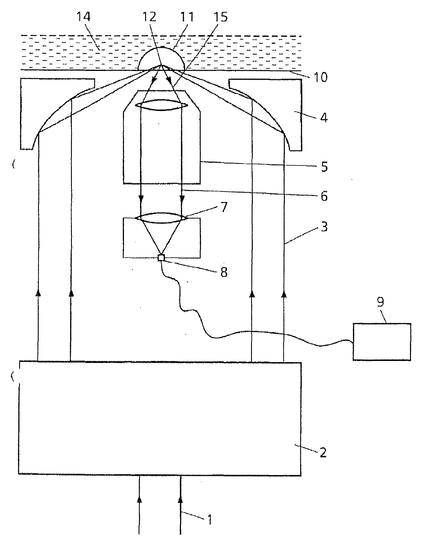
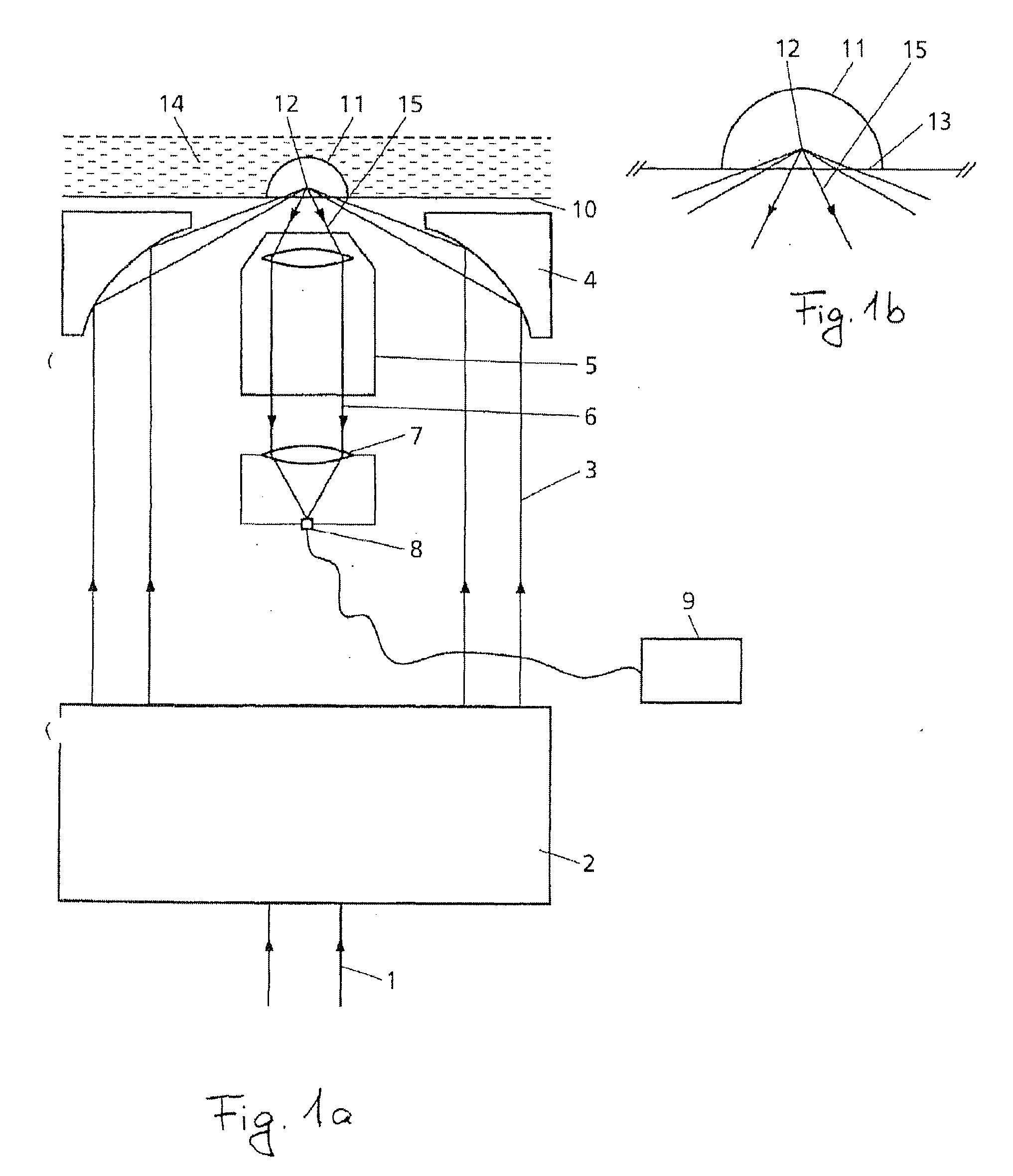
The curved surfaces caused by the drop shape cause hardly controllable reflections when passed by a laser beam, which is why measurements of static light scattering with droplets have not been performed to date or appeared to be impossible.
The Wyatt Technology Corporation offers a light scattering measuring device for use in microtitration plates, which is only able to perform dynamic measurements, however, not static ones.
However, the device of the Wyatt Technology Corporation is not able to suppress disturbing reflections so strongly as would be necessary for performing measurements of static light scattering.

Method used


Image

  • Device and method for measuring static and dynamic scattered light in small volumes
  • Device and method for measuring static and dynamic scattered light in small volumes
  • Device and method for measuring static and dynamic scattered light in small volumes

Examples


Embodiment Construction

[0014]The solution to this technical problem is achieved by a device, a measuring system and a process according to the independent claims. Advantageous embodiments and further embodiments are stated by the dependent claims or can be seen from the following description and exemplary embodiments.

[0015]The present device for performing light scattering measurements comprises at least one focusing element by means of which electromagnetic radiation can be focused onto a sample, a detector, and a detection optical system by means of which electromagnetic radiation scattered by the sample can be guided to the detector. According to the invention, it has been recognized that the technical problem can be solved by providing that the device additionally comprises a means for generating an annular beam, that said at least one focusing element can cause the annular beam to be focused on a focal point within the sample, and that the detection optical system can detect electromagnetic radiation...


PUM


Abstract

The invention relates to a device for measuring scattered light, comprising at least one focusing element provided with electromagnetic radiation that can be focused on a sample, a detector and a detector optical system with which electromagnetic radiation scattered by the sample can be conducted to the detector. The device is characterized in that it comprises means for forming an annular beam such that said annular beam can be focused on a focus point inside the sample by the at least one focusing element and that electromagnetic radiation scattered by the sample can be detected by the detection optical system, said electromagnetic radiation dispersing inside the area surrounded by the annular beam.

Description

TECHNICAL FIELD OF APPLICATION[0001]The present invention relates to a device, a measuring system and a process for performing light scattering measurements, especially measurements of static and dynamic light scattering. Preferred fields of application are those in which it is required to perform a large number of measurements in automated operations, such as in the examination of crystallization processes when protein crystals are to be grown.DESCRIPTION OF RELATED ART[0002]Light scattering measurements, especially laser light scattering measurements, are already being employed in a wide variety of fields of application, for example, for the characterization of colloids. In the food industry, for cosmetic products or also for polymers or adhesives, the size distribution and stability of colloidal particles play an important role.[0003]Another field of application is the elucidation of the structures of complex proteins and other biomolecules, which is of great importance to the we...

Claims


Application Information

Patent Timeline
IPC IPC(8): G01J3/28G01N21/47
CPCG01N21/474G02B21/06G02B21/02G01N2021/4759
Inventor JANZEN, CHRISTOPHNOLL, REINHARDUHL, WALTERHOFFMANN, KURT
Owner HOFFMANN KURT
Learn More