
Disc drying device and disc drying method

a drying device and disc technology, applied in drying machines, lighting and heating apparatus, furniture, etc., can solve the problems of reducing the throughput of the whole disc cleaning process including drying, affecting the efficiency of batch processing, and affecting the drying efficiency of the disc, so as to facilitate the loading and unloading of the discs. , the effect of improving the efficiency of the batch process

Inactive Publication Date: 2010-12-23
HITACHI HIGH-TECH CORP
View PDF1 Cites 5 Cited by
  • Summary
  • Abstract
  • Description
  • Claims
  • Application Information

AI Technical Summary

Benefits of technology

[0010]Accordingly, the present invention addresses the above-described problems in the related art, and an object of the invention is to provide a disc drying device that allows simultaneous and quick drying of plural discs by a batch process and miniaturization of the device.
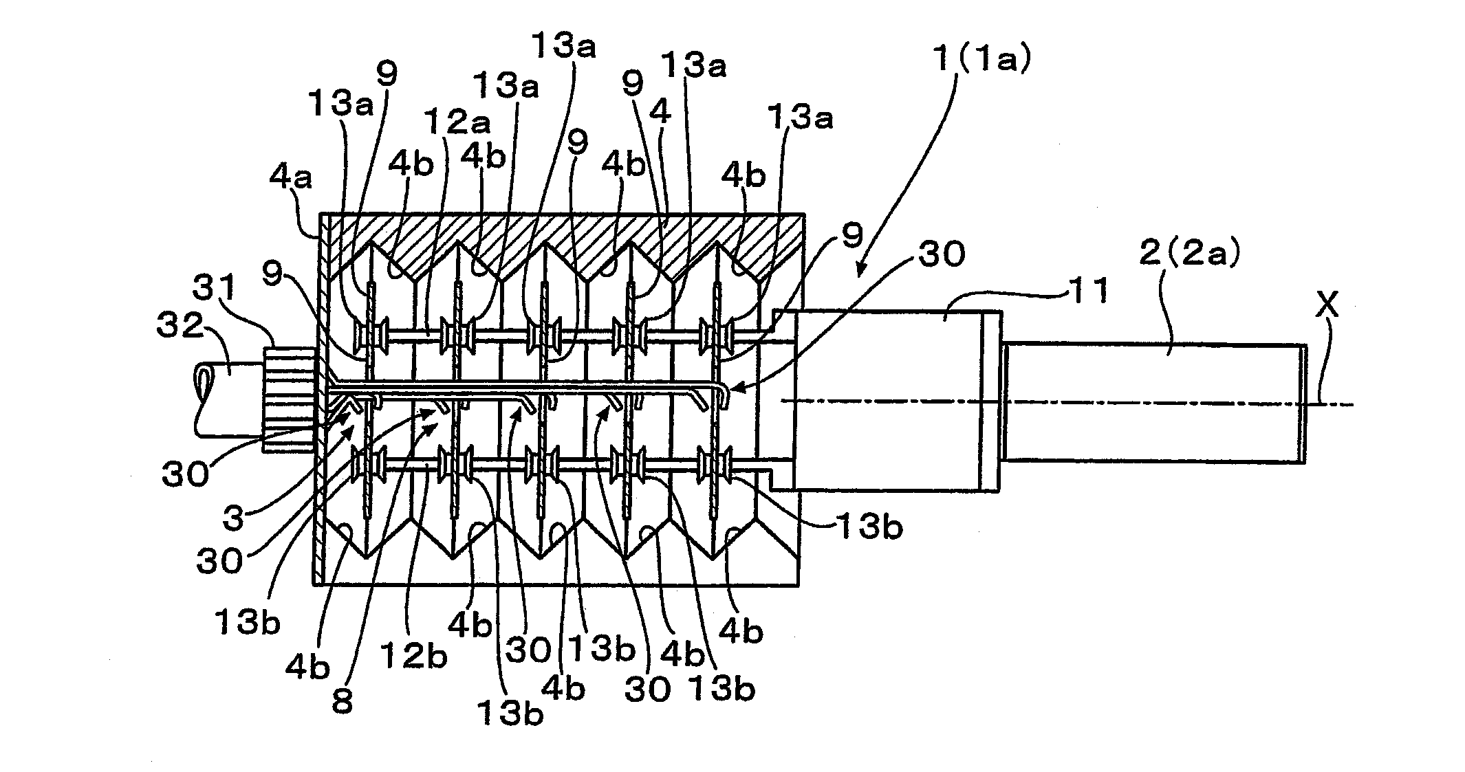
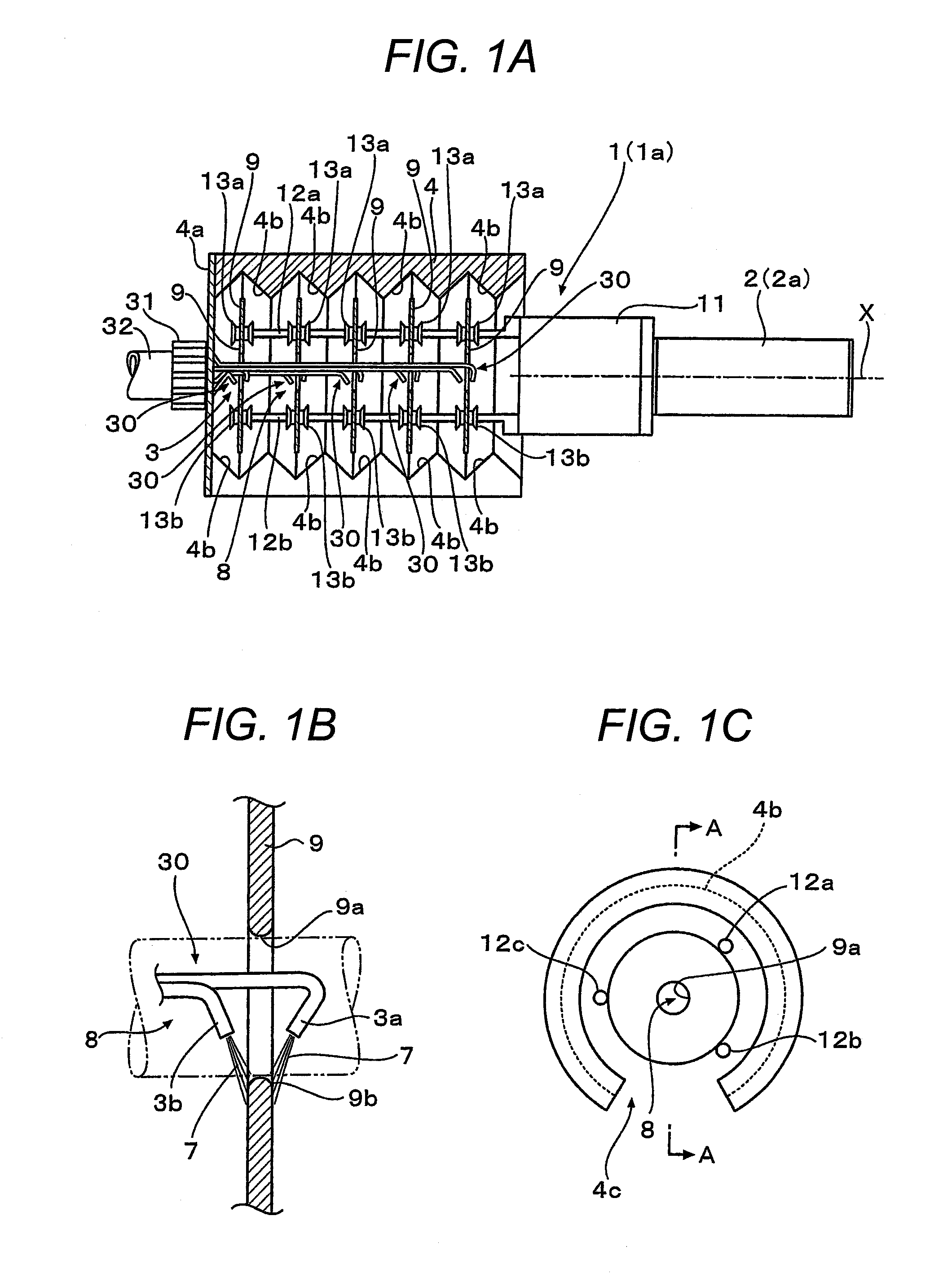
[0012]A feature of a disc drying device and a disc drying method according to the present invention for achieving such object includes: simultaneously chucking, with a disc chuck mechanism, outer peripheries of plural the discs erected with respective centers of the discs arranged along a single axis, leaving a predetermined space therebetween; externally and removably covering the plural chucked discs with a cylindrical water receiving cover with valley grooves being formed circumferentially in a plane perpendicular to the cylindrical axis in an inner wall surface of the water receiving cover; inserting plural pairs of nozzles, in a removable manner with respect to the discs, into a space formed by the central openings of the chucked discs, and placing each of the pairs of nozzles corresponding to two sides of an inner peripheral surface adjacent to the central opening of each of the discs; rotating the disc chuck mechanism to rotate, about the centers of the discs, the discs with the pairs of nozzles and the water receiving cover mounted, and supplying hot water from the pairs of nozzles to heat the chucked discs; causing the hot water to flow from the inner peripheral surfaces to the outer peripheries of the discs by centrifugal force and to be outwardly discharged; and causing the discharged hot water to flow through the valley grooves and to be discharged to the outside from the water receiving cover.
[0014]The discharged hot water flows through valley grooves provided in inner wall surfaces of a water receiving cover to the lower side of the discs to be discharged to the outside. Thus, it is possible to prevent the hot water from dripping on the discs during or after cleaning of the discs and to quickly dry by heating, after stopping the hot water, the discs heated along with the dirt cleaning.
[0017]Also, the pairs of nozzles are inserted into the space formed by the central openings of the chucked discs in such a manner that the pairs of nozzles are removably mounted on the discs along with the water receiving cover. This allows miniaturization of the whole drying device.
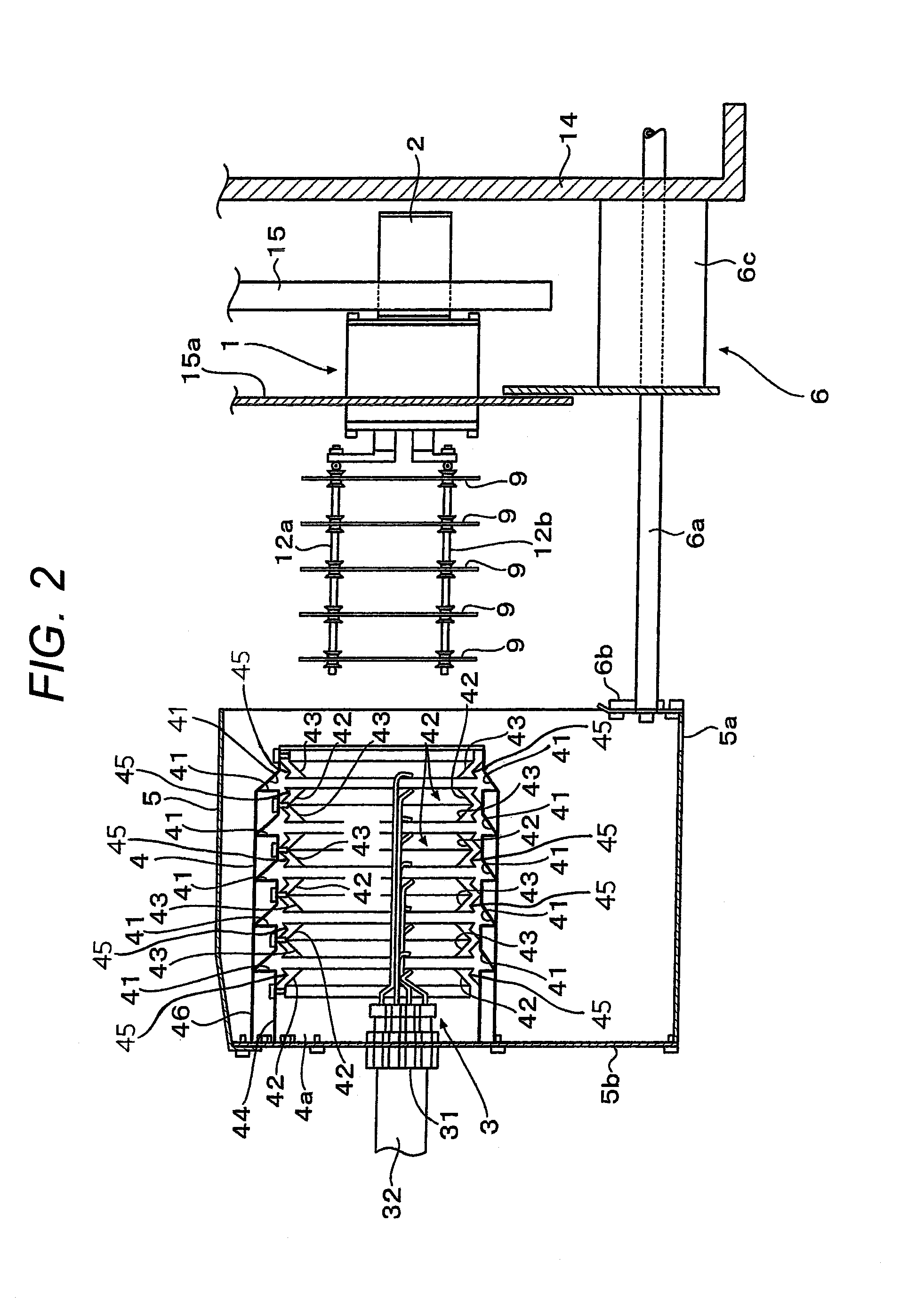
[0018]The arrangement may be such that there is further provided an advancing / retreating mechanism for advancing and retreating the nozzles and the water receiving cover along the single axis with respect to the chucked discs. With this structure, the discs are retreated from the disc chuck mechanism, thereby facilitating loading and unloading of the discs from the disc chuck mechanism. Thus, the efficiency of a batch process may be improved.
[0019]Accordingly, it is possible to realize the disc drying device that allows simultaneous and quick drying of the plural discs by the batch process and is small-sized.

Problems solved by technology

In addition, since the recent drying process includes a rinsing process and a spin-drying process, there has been a problem that dirt also adheres to the discs in the delivery process for transferring from the rinsing process to the spin-drying process.
This processing time causes a decrease in throughput of the whole disc cleaning processing including drying.
In such a disc cleaning and drying device, however, the number of processable discs is limited to two or three at a time, and cleaning processing efficiency per disc is not much improved.
Additionally, one problem is that, to process multiple discs at a time in such a device, upsizing of the device is required.

Method used


Image

  • Disc drying device and disc drying method
  • Disc drying device and disc drying method
  • Disc drying device and disc drying method

Examples


Embodiment Construction

[0028]In FIG. 3, reference sign 10 denotes a disc drying device; 1 and 1a denote disc chuck mechanisms of the disc drying device 10; 2 and 2a denote rotary drive mechanisms (drive motors) of the disc chuck mechanisms 1 and 1a; 3 denotes a hot-water supply nozzle unit (see FIG. 1A); 4 denotes a water receiving cover (see FIG. 1A); 5 denotes an enclosure; 6 denotes a water receiving cover advancing / retreating mechanism; and 9 denotes a disc (see FIG. 1A).

[0029]Referring to FIGS. 1A to 1C, the disc chuck mechanism 1 is composed of a chuck opening and closing mechanism 11 and three chuck arms 12a, 12b, and 12c, and holds the five (plural) discs 9 using an outer circumferential three-point chuck (see FIG. 1C), with the discs 9 being erected with respective centers thereof arranged along X axis, leaving a predetermined space therebetween.

[0030]It should be noted that FIG. 1A is a sectional view taken along the arrowed line A-A of FIG. 1C and therefore the chuck arm 12c does not appear in ...


PUM


Abstract

The present invention provides a disc drying device and a disc drying method that allow simultaneous and quick drying of plural discs by a batch process and realize miniaturization of the device. In the present invention, plural discs arranged along a single axis are simultaneously chucked at outer peripheries thereof so that central openings of the discs internally form a space; plural nozzles are disposed in the space so as to supply hot water from inner peripheral surfaces of two sides of each of the discs to heat the discs with the hot water; and the discs are simultaneously rotated to thereby move the hot water from inner peripheries to outer peripheries of the discs and discharge the hot water outwardly of the outer peripheries by centrifugal force. The discharged hot water flows through valley grooves provided in inner wall surfaces of a water receiving cover to the lower side of the discs to be discharged to the outside.

Description

BACKGROUND OF THE INVENTION[0001]1. Field of the Invention[0002]The present invention relates to a disc drying device and a disc drying method, and more particularly, to a disc drying device that allows simultaneous and quick drying of plural discs by a batch process and miniaturization of the device.[0003]2. Description of the Related Art[0004]In the case of substrates for magnetic discs (hard discs) as information recording media, cleaning of the discs has been performed after the process of grinding, polishing, spattering and plating. For the cleaning of hard discs and substrates therefor (hereinafter these will be simply referred to as discs), plural cleaning processes and drying processes after the cleaning are provided.[0005]Typically, the drying process is independent of the cleaning process. The discs after cleaning are immersed in a pure water container and then taken out therefrom to be subjected to the drying process so as to prevent cleaning liquid from remaining after t...

Claims


Application Information

Patent Timeline
Patent Type & Authority Applications(United States)
IPC IPC(8): F26B5/08F26B17/30
CPCF26B3/00F26B7/00F26B5/08
Inventor MARUYAMA, MAKOTORATTRAY, BRIAN
Owner HITACHI HIGH-TECH CORP
Learn More