Wave Gear Device

Active Publication Date: 2010-12-23
HARMONIC DRIVE SYST IND CO LTD
View PDF11 Cites 23 Cited by
  • Summary
  • Abstract
  • Description
  • Claims
  • Application Information

AI Technical Summary

Benefits of technology

[0031]In the wave gear device of the present invention, a tooth profile in which the tooth depth is kept constant and in which the bottom land and top land are parallel to each other along the direction of the flank line is used as the basic tooth profile for the circular spline and the flexspline. A taper is formed on a part of the top land at the flank line end near the open end of the spline

Problems solved by technology

As a result of coning, the tip surfaces of the teeth of one spline end up interfering with the bottom lands of the teeth of the other spline at the open end of the flexspline, and satisfactory meshing cannot be obtained in a case in which the tooth profiles of the two splines are designed so that the teeth have the same depth in the tooth trace

Method used


Image

  • Wave Gear Device
  • Wave Gear Device
  • Wave Gear Device

Examples


Embodiment Construction

[0037]A wave gear device to which the present invention is applied is described below with reference to the accompanying drawings.

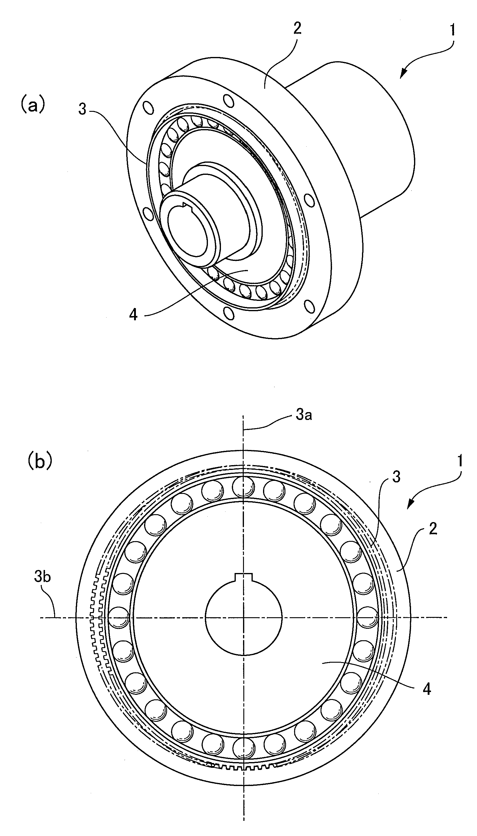
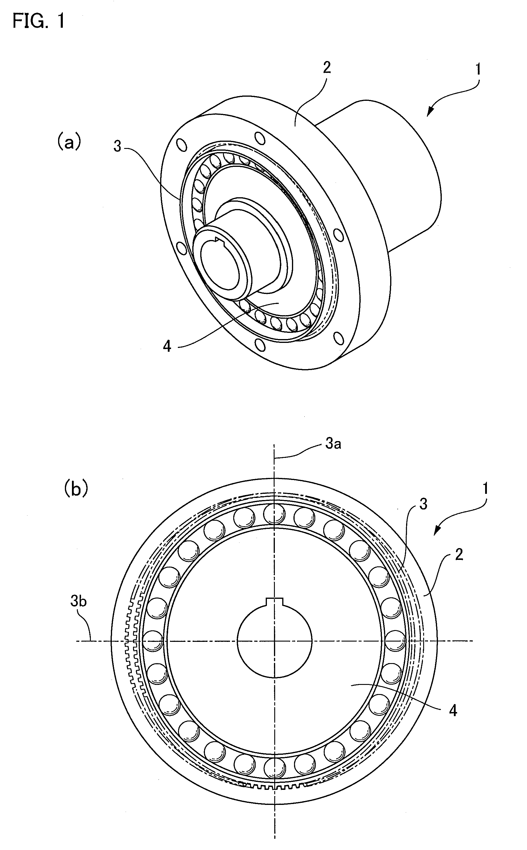
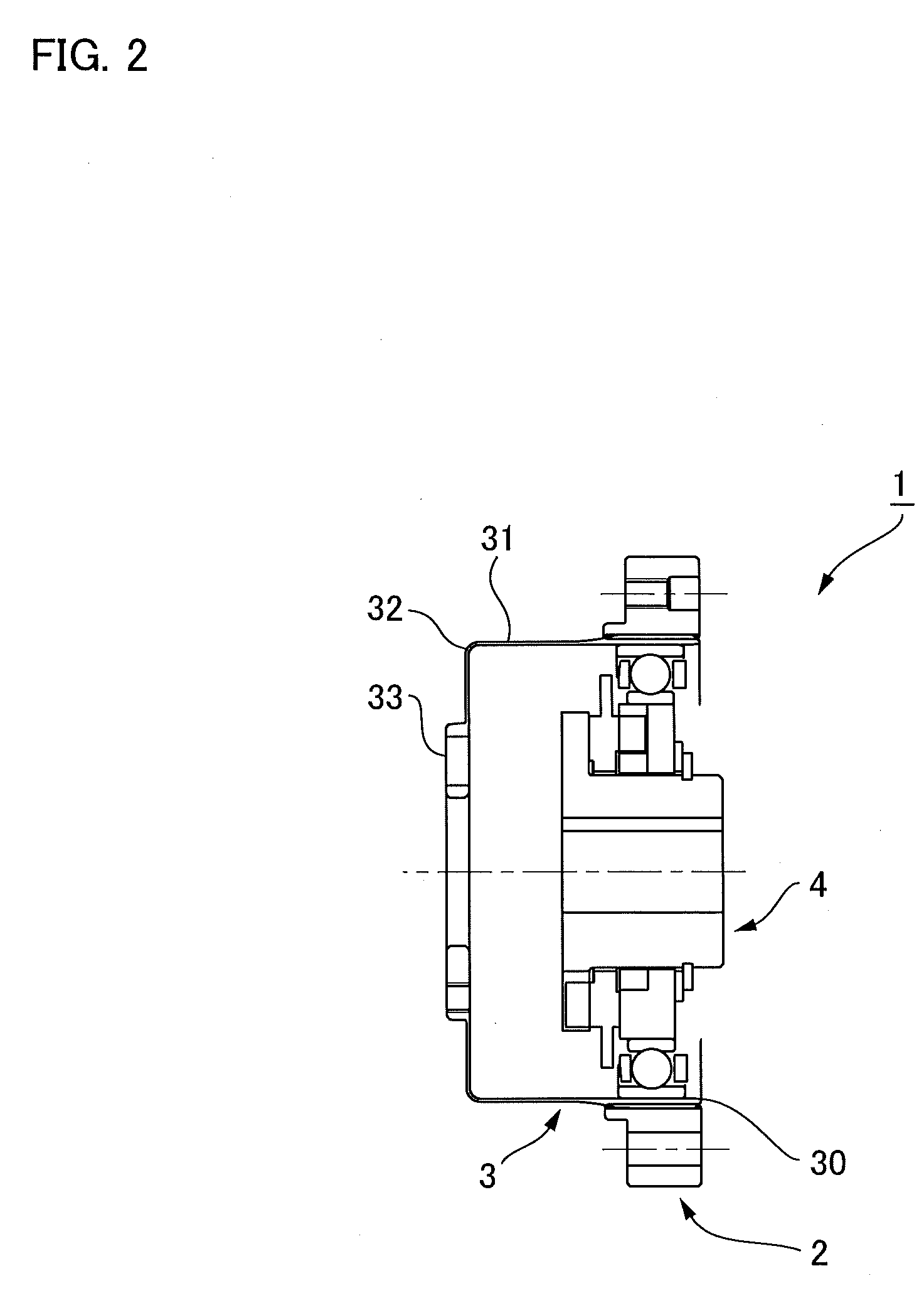
[0038]FIGS. 1 and 2 are a longitudinal sectional view and a schematic front view showing a cup-type wave gear device. The cup-type wave gear device 1 comprises a rigid circular spline 2, a cup-shaped flexspline 3 disposed inside the circular spline, and an elliptical wave generator 4 mounted inside the flexspline. The cup-shaped flexspline 3 is bent into an elliptical shape by the wave generator 4. When the wave generator 4 rotates, the positions where the two splines are enmeshed move in a circumferential direction, and relative rotation is generated between the two splines 2, 3 in accordance with the difference in the number of teeth between the splines 2, 3.

[0039]FIG. 3 is an explanatory view showing a state in which the flexspline 3 is bent by coning, wherein (a) is a longitudinal sectional view showing the state before deformation, (b) is a longitudi...


PUM

PropertyMeasurementUnit
Depthaaaaaaaaaa
Distanceaaaaaaaaaa

Abstract

A bending state known as “coning,” in which the amount of bending of the flexspline gradually decreases in accordance with the distance from the open end of the spline, occurs in cup-type or “silk hat”-type wave gear devices. A tooth profile in which the tooth depth is kept constant and in which the bottom lands and top lands are parallel to each other along the tooth trace direction is used as the basic tooth profile for the circular spline and the flexspline of the wave gear device. A taper surface is formed on a part of the top land near the open end of the flexspline in the basic tooth profile, whereby a modified tooth profile is obtained. The modified tooth profile is employed as the tooth profile for both of the splines. Both of the splines can be caused to mesh together without generating coning-induced interference. Both of the splines can also be subjected to gear cutting by a simple process using a typical machining mechanism.

Description

TECHNICAL FIELD[0001]The present invention relates to a wave gear device in which a cup-shaped or “silk hat”-shaped flexspline is bent into an elliptical shape to mesh with a circular spline in areas on either end of the major axis of the elliptical shape, and the positions where the two splines are enmeshed are caused to move in a circumferential direction, thereby generating relative rotation between the two splines in accordance with the difference in the number of teeth between the two splines. The present invention more particularly relates to a wave gear device having an external teeth profile and internal teeth profile that makes it possible for the external teeth of the cup-shaped or “silk hat”-shaped flexspline, bent in a state in which the amount of bending gradually increases in a radial direction toward the open end of the flexspline, to mesh with the internal teeth of the circular spline without interference.BACKGROUND ART[0002]Cup-type wave gear devices having cup-shap...

Claims


Application Information

Patent Timeline
IPC IPC(8): F16H35/00B23P15/14B23F15/00
CPCF16H49/001F16H55/0833F16H2049/003Y10T29/49478Y10T74/19Y10T74/19972Y10T409/101431Y10T29/49476F16H1/32
Inventor KANAI, SATORU
Owner HARMONIC DRIVE SYST IND CO LTD
Why Eureka
Try Eureka