

Heat sink and method of manufacture thereof
a technology of heat sink and heat sink body, which is applied in the direction of solid-state devices, lighting and heating apparatus, and semiconductor/solid-state device details, etc., and can solve the problems of cooling fluid leakage, damage to the pipe, and pipe damag
- Summary
- Abstract
- Description
- Claims
- Application Information
AI Technical Summary
Benefits of technology
Problems solved by technology
Method used
Image

Examples
Embodiment Construction
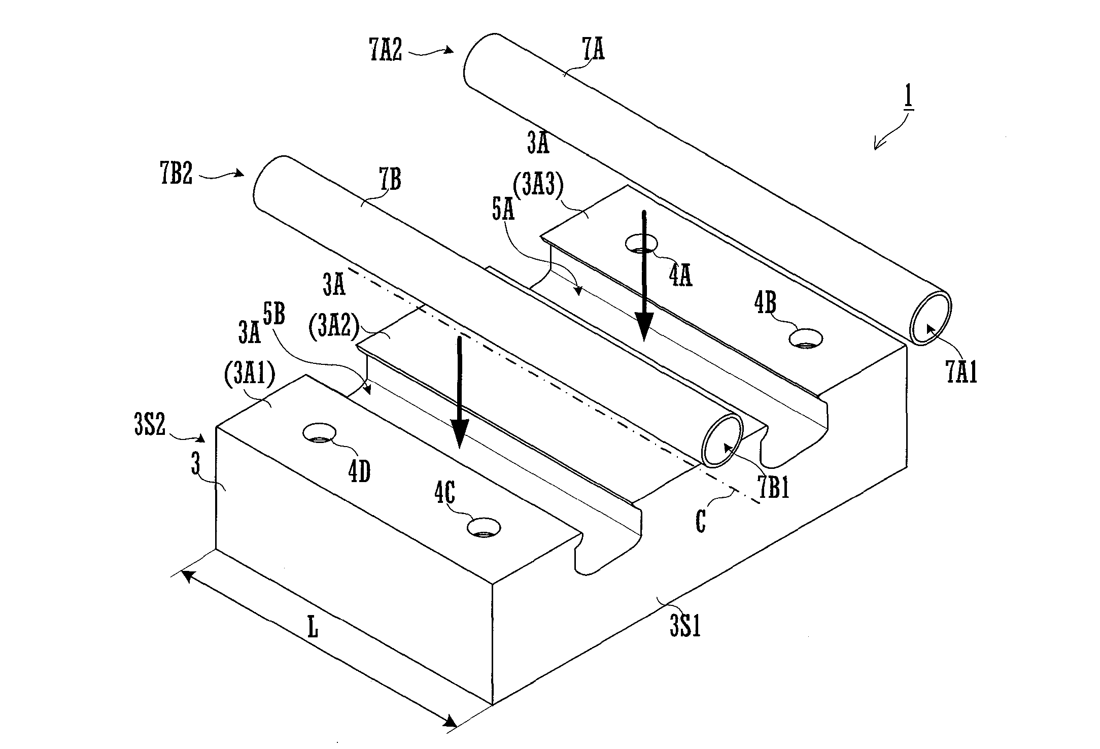
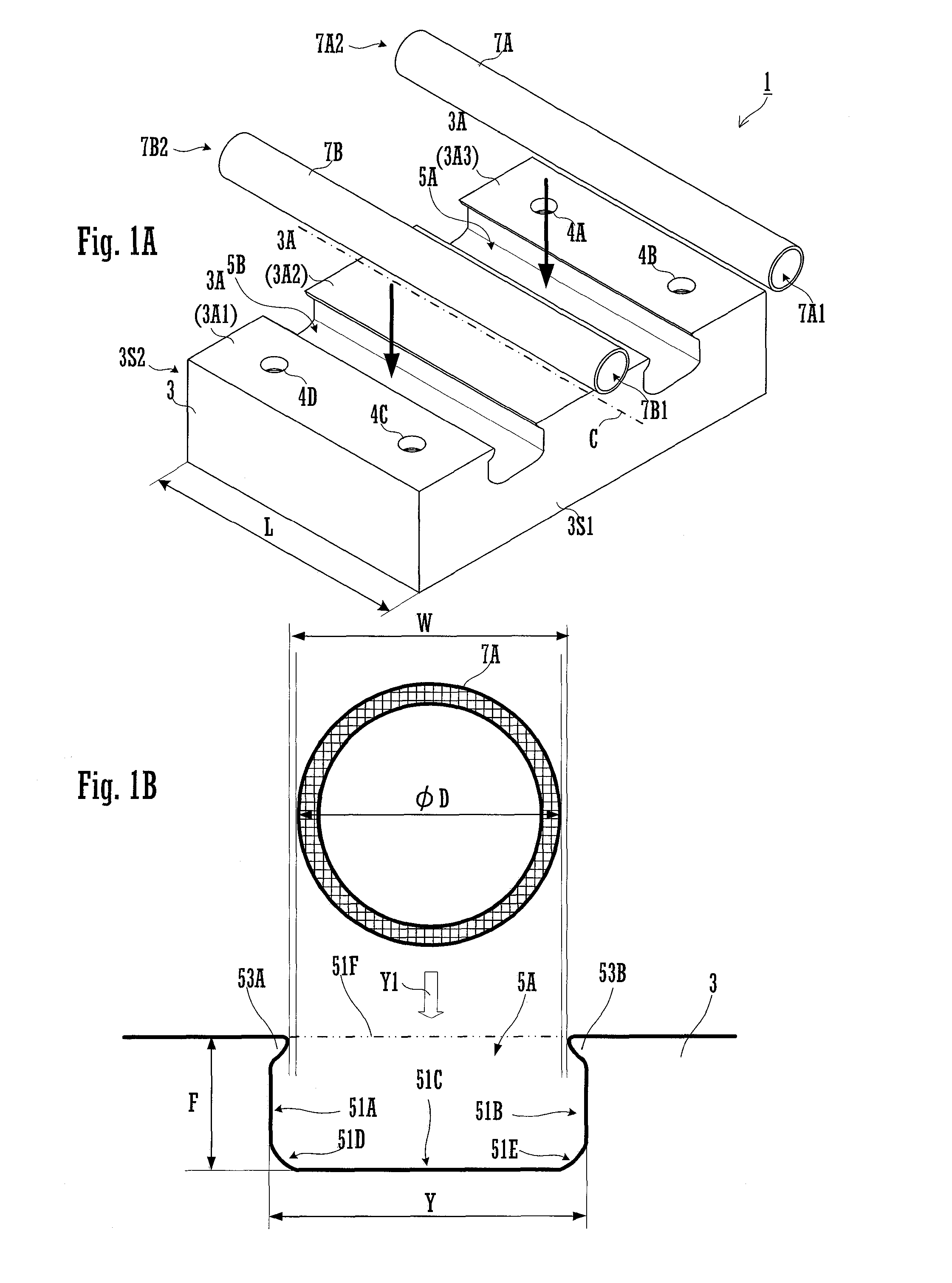
[0018]FIGS. 1A and 1B are respectively a perspective view of a base and pipes of a heat sink manufactured by the method of manufacture of the present invention before assembly, and an enlarged partial sectional elevation view thereof.
[0019]As shown in FIG. 1A, this heat sink 1 comprises a base 3, a pipe 7A, and a pipe 7B.
[0020]The base 3 is a block (a plate) made from aluminum or aluminum alloy, and is provided with grooves 5A and 5B that have exposed sides (exposed faces) at a contacting face 3A that is contacted against a thermal component 9 such as a semiconductor (for example an IGBT) or the like (refer to FIG. 4B). A pipe 7A is fitted into this groove 5A, and a pipe 7B is fitted into the groove 5B. Furthermore, the groove 5A and the groove 5B are provided in positions that contact against the bottom surface of the thermal component 9, so that, when the thermal component 9 is contacted against the contacting face 3A, it is possible to cool the thermal component 9 with good effic...
PUM
| Property | Measurement | Unit |
|---|---|---|
| diameter | aaaaa | aaaaa |
| processing accuracy | aaaaa | aaaaa |
| pressure | aaaaa | aaaaa |
Abstract
Description
Claims
Application Information