Supercharge Your Innovation With Domain-Expert AI Agents!

Lighting unit and discharge lamp

a discharge lamp and light-emitting unit technology, applied in the field of light-emitting units, can solve the problems of melting, deformation, discoloration, etc., and break down of electrolytic capacitors, and achieve the effects of improving safety, reducing the risk of heat generation after the breakdown, and improving the safety after the breakdown of heat-emitting capacitors

Inactive Publication Date: 2010-12-23
PANASONIC CORP
View PDF9 Cites 1 Cited by
  • Summary
  • Abstract
  • Description
  • Claims
  • Application Information

AI Technical Summary

Benefits of technology

This solution effectively terminates circuit operation safely without additional components, reducing the risk of heat-related damage to the lamp's case and improving safety without increasing costs, while allowing for more compact designs by minimizing heat generation post-breakdown.

Problems solved by technology

In the event that any of electrodes of an arc tube or any electronic component (hereinafter, referred to simply as “heat generating component”) undergoes an excessive temperature rise for some reason, the resulting heat may cause various problems, such as deformation, discoloration, and meltdown of the case.
Thus, when the electrode of the arc tube comes to the end of its useful life, the choke coil generates heat and the resulting heat breaks down the electrolytic capacitor.

Method used


Image

  • Lighting unit and discharge lamp
  • Lighting unit and discharge lamp
  • Lighting unit and discharge lamp

Examples


Embodiment Construction

1. Overall Structure of Lamp

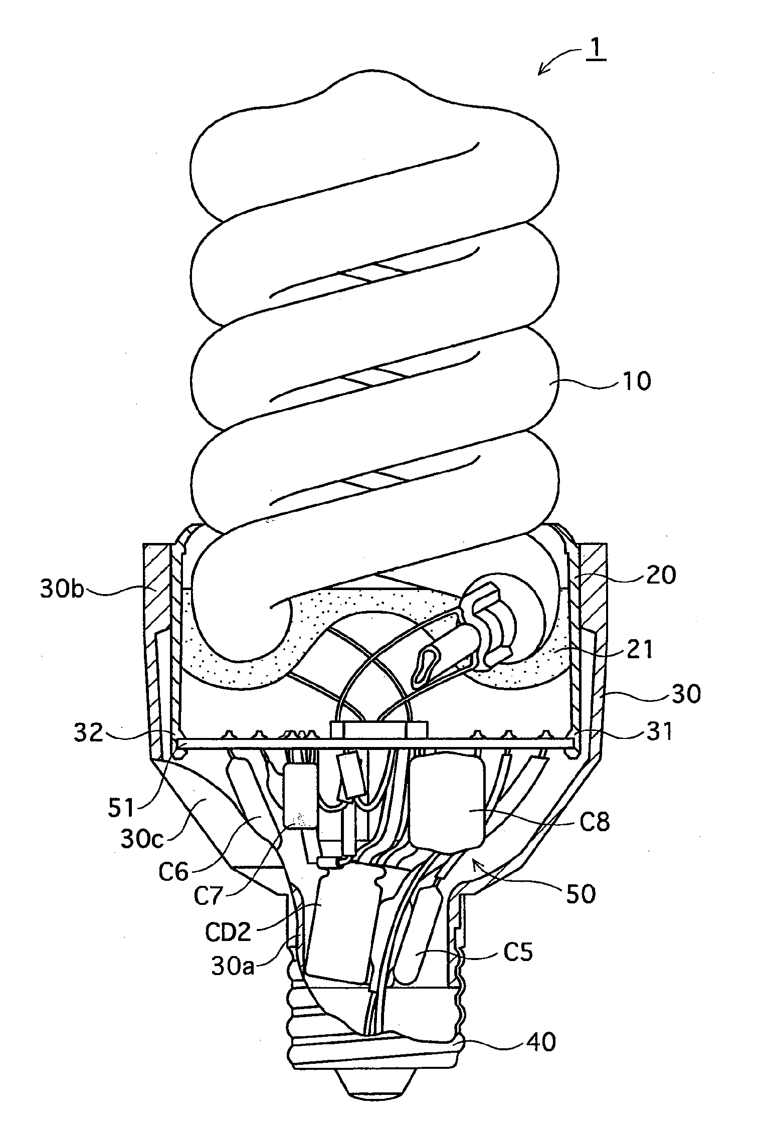
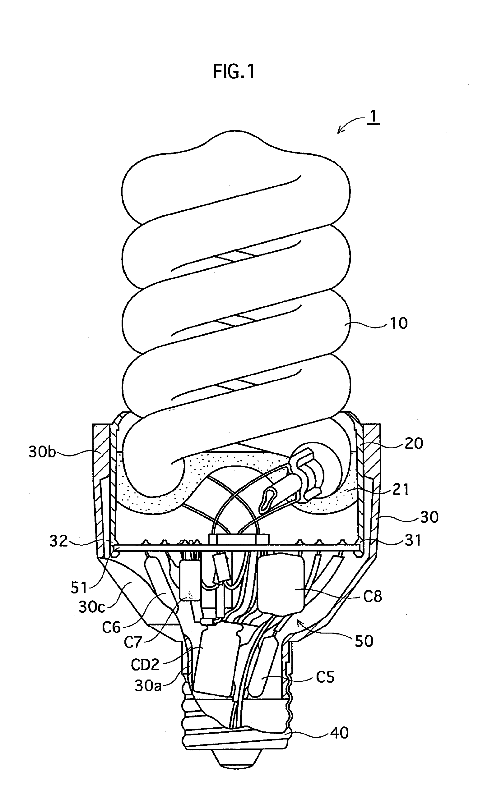
[0059]FIG. 1 is a cross-sectional view of a lamp 1 according to an embodiment of the present invention, as seen from the side. In addition, FIG. 1 is partly broken away to better show internal details. The lamp 1 illustrated in FIG. 1 is a 12-watt lamp, which is a replacement for a 60-watt incandescent lamp.

[0060]As illustrated in FIG. 1, the lamp 1 is roughly composed of an arc tube 10 defining a double-spiral discharge path, a holder 20 for holding the arc tube 10, a lighting unit 50 for causing the arc tube 10 to emit light, a case 30 disposed to house the holder 20 and the lighting unit 50 therein, and a base 40 attached to one end of the case 30. Note that the holder 20 and the case 30 together constitute the “case” according to the present invention.

[0061]The arc tube 10 is composed of a glass tube (having an outside diameter of 9.0 mm, for example) that is made from soft glass. The glass tube is so processed to have a bend at a substantially middle...


PUM

PropertyMeasurementUnit
inrush currentaaaaaaaaaa
fluorescentaaaaaaaaaa
positive temperature coefficientaaaaaaaaaa

Abstract

Provided is a lighting unit and a discharge lamp each of which is capable of causing a capacitor to break down by heat generated in a heat generating component, so that circuit operation is safely terminated without any additional cost. A compact self-ballasted fluorescent lamp is provided with a lighting unit (50) housed in a case. The lighting unit (50) causes an arc tube to emit light and is composed of a plurality of electronic components, including a rectifier / smoothing circuit portion, an inverter circuit portion having transistors (Q1 and Q2), a resonant circuit portion, and a preheating circuit portion having a positive temperature coefficient element. Among the plurality of electronic components, the transistors (Q1 and Q2) and the positive temperature coefficient element generate excessive heat when, for example, the lamp is operated at the end of electrode's life. Capacitors (C4 and C6) disposed in the vicinity of the positive temperature coefficient element would break down by heat in a short mode.

Description

RELATED APPLICATIONS[0001]This is a divisional application of U.S. Ser. No. 11 / 817,140, filed on Aug. 24, 2007, which is a National Phase Application of PCT / JP2006 / 303945 filed on Mar. 2, 2006, which claims priority from Japanese Application No. 2005-058223 filed Mar. 2, 2005 and Japanese Application No. 2006-055118 filed Mar. 1, 2006.TECHNICAL FIELD[0002]The present invention relates to a lighting unit for a lamp and also to a discharge lamp having the lighting unit. More specifically, the present invention relates to a lighting unit of an inverter type.BACKGROUND ART[0003]In response to the recent demand for energy savings, an increasing number of low-pressure mercury discharge lamps, which have high-efficiency and long rated life, are replacing conventionally used incandescent lamps.[0004]A compact self-ballasted fluorescent lamp (hereinafter, referred to simply as a “lamp”) is roughly composed of an arc tube, a lighting unit for operating the arc tube, and a resinous case for ho...

Claims


Application Information

Patent Timeline
Patent Type & Authority Applications(United States)
IPC IPC(8): F21V23/00
CPCH01J61/327H01J61/56H05B41/298H05B41/2988H05K2201/10522H05K1/18H05K2201/10015H05K2201/10022H05K2201/10166H05K1/0201
Inventor MORIMOTO, ETSUJIITOU, KAZUHIKOGYOTEN, MASAYOSHITAKAHASHI, AKIRA
Owner PANASONIC CORP
Features
  • R&D
  • Intellectual Property
  • Life Sciences
  • Materials
  • Tech Scout
  • Unparalleled Data Quality
  • Higher Quality Content
  • 60% Fewer Hallucinations
Learn More