Power Reforming Methods and Associated Multiphase Lights

a technology of power reforming and multi-phase lights, applied in the direction of electroluminescent light sources, ac network voltage adjustment, electric lighting sources, etc., can solve the problems of inefficiency in shedding waste heat, significant power loss, and still has some drawbacks, and achieves a better power factor

Inactive Publication Date: 2010-12-23
GRAY RICHARD LANDRY
View PDF2 Cites 51 Cited by
  • Summary
  • Abstract
  • Description
  • Claims
  • Application Information

AI Technical Summary

Benefits of technology

[0009]The present invention has several objectives, which generally relate to a power reforming method and associated multiphase lights that selectively turn ON and OFF to reform current that provides better power factor, heat dissipation and color mixing.

Problems solved by technology

Significant power losses can occur from the source of the power to where the power is ultimately consumed, at the load.
However, the LED still has some drawbacks that are caused by their inability to efficiently shed their waste heat.
If they have different dimming frequencies, the multiple lamps used in the room may appear to flicker due to the “beating” phenomenon.
For lighting applications the difference frequency causes the most problems because, if the initial signal frequencies only vary by a few cycles per second, then the difference frequency is well within a human's ability to perceive it.
This “beating” problem, no matter what type of light is used, happens very often when the dimming frequencies of different lamps are not synchronized in some way.
Normal variations in electronic processing make it extremely difficult to match the frequencies of two independent groups of electronics without using very accurate, expensive techniques.

Method used


Image

  • Power Reforming Methods and Associated Multiphase Lights
  • Power Reforming Methods and Associated Multiphase Lights
  • Power Reforming Methods and Associated Multiphase Lights

Examples


Embodiment Construction

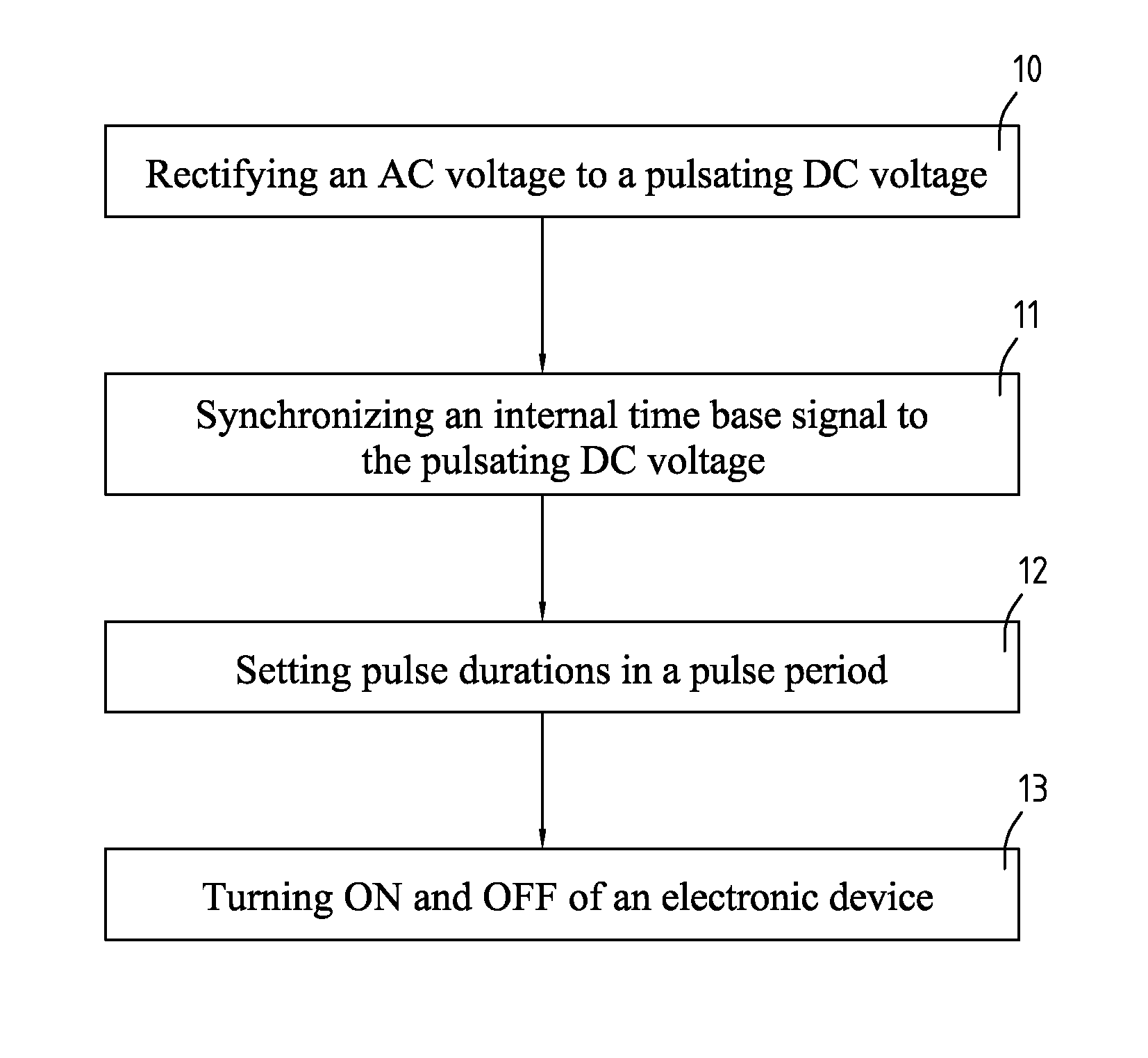
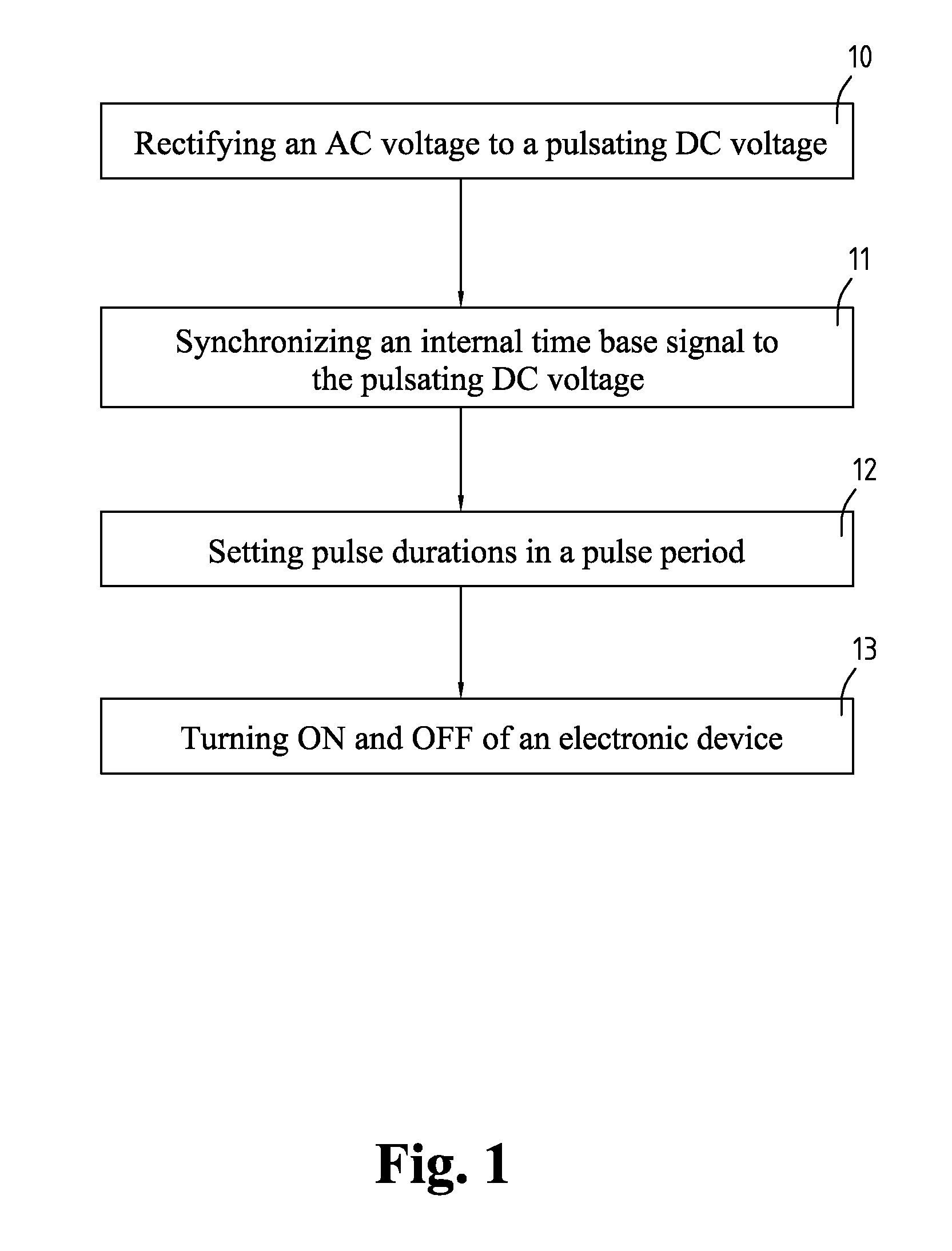
[0039]With reference to FIG. 1, a power reforming method for an electronic device in accordance with the present invention comprises acts of rectifying an alternating current (AC) voltage to a pulsating direct current (DC) voltage (10), synchronizing an internal time base signal to the pulsating DC voltage (11), setting pulse durations in a pulse period (12) and turning ON and OFF of an electronic device (13).

[0040]The act of rectifying an AC voltage to a pulsating DC voltage (10) rectifies an AC voltage to a pulsating DC voltage. The frequency of the AC voltage is often 60 Hz for many commercial and residential applications.

[0041]The act of synchronizing the pulsating DC voltage (11) synchronizes the phase of an internal time base signal to the pulsating DC voltage.

[0042]The act of setting pulse durations in a pulse period (12) sets at least one rising time and at least one falling time of at least two control signals corresponding to the internal time base signal.

[0043]The interna...


PUM


Abstract

The present invention relates to power reforming methods and associated multiphase lights, especially to power reforming methods and associated multiple lights that selectively turn ON and OFF to reform current to follow voltage appropriately, which provides better heat dissipation, improving power factor and color mixing capability. The method comprises acts of rectifying an AC voltage to a pulsating DC voltage, synchronizing an internal time base signal to the pulsating DC voltage, setting pulse duration in a pulse period and turning ON and OFF of an electronic device. The device comprises at least two loads, a rectifier, at least two drivers and a controller.

Description

CROSS REFERENCE TO RELATED APPLICATIONS[0001]This application claims priority and is filed as Continuation in Part (CIP) to U.S. patent application Ser. No. 12 / 770,727 filed on Apr. 30, 2010 and claims priority to U.S. provisional patent applications No. 61 / 219,337 filed on Jun. 22, 2009, 61 / 220,582 filed on Jun. 26, 2009, and 61 / 236,757 filed Aug. 25, 2009, which applications are hereby incorporated by this reference in their entireties.FIELD OF THE INVENTION[0002]The present invention relates to power reforming methods and associated multiphase lights, especially to power reforming methods and associated multiple lights that selectively turn ON and OFF to reform current to follow an input voltage more appropriately, which provides better heat dissipation, improving power factor and color mixing capability.BACKGROUND OF THE INVENTION[0003]The optimal situation for power transfer to a load connected to a line voltage (i.e. a 60 Hz alternating current (AC) power source used in a hous...

Claims


Application Information

Patent Timeline
Patent Type & Authority Applications(United States)
IPC IPC(8): H05B37/02H02J1/00
CPCH02M1/4208Y02B70/126H05B33/0818H02M3/3376Y02B70/10H05B45/46H05B45/325
Inventor GRAY, RICHARD LANDRYTSAI, PO MING
Owner GRAY RICHARD LANDRY
Why Eureka
Try Eureka