Charge control circuit

a control circuit and circuit technology, applied in the direction of transportation and packaging, secondary cell servicing/maintenance, sustainable buildings, etc., to achieve the effect of reducing the number of parts, reducing power losses, and eliminating the occurrence of loss

Inactive Publication Date: 2010-12-23
RICOH KK
View PDF3 Cites 58 Cited by
  • Summary
  • Abstract
  • Description
  • Claims
  • Application Information

AI Technical Summary

Benefits of technology

[0021]According to a charge control circuit of the embodiments of the present invention, a control circuit part performs PWM control for constant voltage output operations with respect to a switching element using a current mode control method in which a current sense voltage is used at the time of constant voltage charging in which a constant voltage is supplied to a secondary battery for charging, and the control circuit part performs PWM control for constant current output operations with respect to the switching element at the time of constant current charging in which a constant current is supplied to the secondary battery for charging. The control circuit part compares the current sense voltage with a fourth reference voltage generated by adding a difference voltage between a second predetermined reference voltage and the current sense voltage to the second reference voltage, and the control circuit part performs the PWM control for the constant current output operations using a pulse signal indicating a comparison result. Therefore, the resistors for detecting a charging current are not required, making it possible to reduce the number of parts and eliminate the occurrence of loss due to the current flowing to the resistors.
[0022]Furthermore, because switching control is performed both in constant current mode and in constant voltage mode where power losses are caused at the time of a boost charge, etc., it is possible to reduce the power losses.

Problems solved by technology

However, due to the resistor used for detecting the charge current, a current flowing through the resistor disadvantageously causes loss.

Method used


Image

  • Charge control circuit
  • Charge control circuit
  • Charge control circuit

Examples


first embodiment

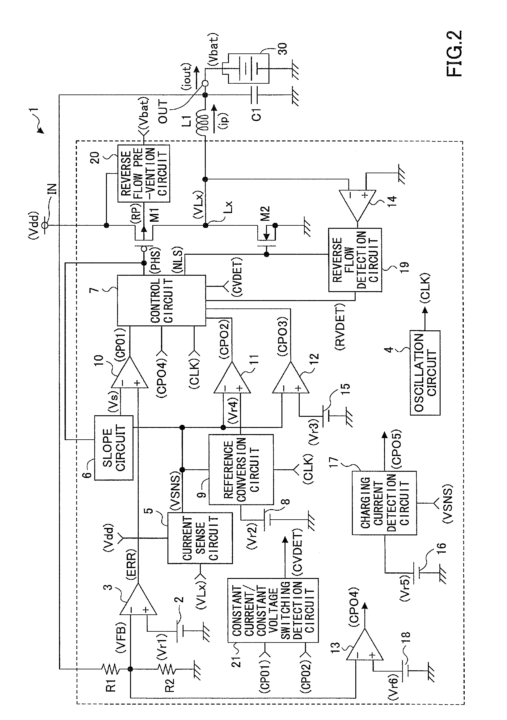
[0034]FIG. 2 is a diagram showing a circuit example of a charge control circuit according to a first embodiment of the present invention.

[0035]In FIG. 2, a charge control circuit 1 includes a non-insulated step-down switching regulator using an inductor and charges a secondary battery 30 connected to an output terminal OUT using a power supply voltage Vdd input to an input terminal IN from an AC adapter, etc., as a power supply.

[0036]The charge control circuit 1 has a switching transistor M1 composed of a PMOS transistor that performs a switching operation for the output control of the power supply voltage Vdd, a synchronous rectification transistor M2 composed of an NMOS transistor, an inductor L1, and a capacitor C1.

[0037]In addition, the charge control circuit 1 has a reference voltage generation circuit 2 that generates and outputs a first predetermined reference voltage Vr1, an error amplification circuit 3, an oscillation circuit 4 that generates and outputs a predetermined cl...

second embodiment

[0092]In the first embodiment, when the battery voltage Vbat is less than the sixth reference voltage Vr6, the constant current operation in the VFM control is performed using the signals CPO3 and RVDET. Alternatively, a constant current circuit that generates and outputs a predetermined constant current may be provided in the charge control circuit. According to a second embodiment of the present invention, when the battery voltage Vbat is less than the sixth reference voltage Vr6, the constant current circuit supplies a constant current to the secondary battery 30.

[0093]FIG. 9 is a diagram showing a circuit example of the charge control circuit according to the second embodiment of the present invention. Note that in FIG. 9 parts the same as or similar to those of FIG. 2 are denoted by the same reference numerals and a description thereof is omitted. Here, only differences between them are described.

[0094]FIG. 9 is different from FIG. 2 in that it eliminates the comparator 12 and ...


PUM


Abstract

When a control circuit detects from a signal CPO4 that a battery voltage is less than a sixth reference voltage, a constant current operation in VFM control is performed with respect to a switching transistor and a synchronous rectification transistor in accordance with signals RVDET and CPO3. Furthermore, when the control circuit detects from the signal CPO4 that the battery voltage becomes equal to or greater than the sixth reference voltage, the constant current operation in PWM control is performed in accordance with a signal CPO2. When an output signal CVDET from a constant current/constant voltage switching detection circuit becomes high level, operation control with respect to the switching transistor and the synchronous rectification transistor is switched from the PWM control of constant current operations to the PWM control of constant voltage operations in accordance with a signal CPO1.

Description

TECHNICAL FIELD[0001]The present invention relates to a charge control circuit that charges a secondary battery by using a switching regulator.BACKGROUND ART[0002]FIG. 1 is a diagram showing an example of a conventional charge control circuit that uses a switching power supply and a linear voltage regulator together (see, for example, Patent Document 1).[0003]The charge control circuit shown in FIG. 1 attempts to improve power efficiency by operating either the switching power supply or the linear voltage regulator in a switching manner with the battery voltage of a secondary battery. The detection of a charge current at the time of constant current operations is performed using a voltage difference between both ends of a resistor RSNS connected in series to the secondary battery.[0004]Patent Document 1: JP-A-2007-14163[0005]However, due to the resistor used for detecting the charge current, a current flowing through the resistor disadvantageously causes loss. Moreover, when the res...

Claims


Application Information

Patent Timeline
Patent Type & Authority Applications(United States)
IPC IPC(8): H02J7/04
CPCH01M10/44H02J7/041Y02B70/1466H02M3/1588Y02B40/90H02J7/045H02J7/0071Y02B40/00Y02B70/10Y02E60/10H02J7/04H02J7/007182H02J7/00714
Inventor NISHIDA, JUNJI
Owner RICOH KK
Why Eureka
Try Eureka