Switching converters with efficiently-controlled mode transitions

a technology of switching converters and efficiently controlled modes, applied in the direction of electric variable regulation, process and machine control, instruments, etc., can solve the problems of conduction loss and switching loss, loss limitation, and loss of conduction loss

Active Publication Date: 2010-12-23
ANALOG DEVICES INC
View PDF13 Cites 28 Cited by
  • Summary
  • Abstract
  • Description
  • Claims
  • Application Information

AI Technical Summary

Problems solved by technology

Power losses in these configurations include conduction losses and switching losses.
Conduction losses occur as switched currents pass through the inductor and capacitor and associated interconnecting traces.
These losses can be limited by designing these components (e.g., with ceramic inductors and capacitors) to reduce parameters such as winding loss, core loss, dielectric loss and capacitor leakage.
The control and synchronous transistors also contribute to the switching losses because they pas...

Method used


Image

  • Switching converters with efficiently-controlled mode transitions
  • Switching converters with efficiently-controlled mode transitions
  • Switching converters with efficiently-controlled mode transitions

Examples


embodiment 20

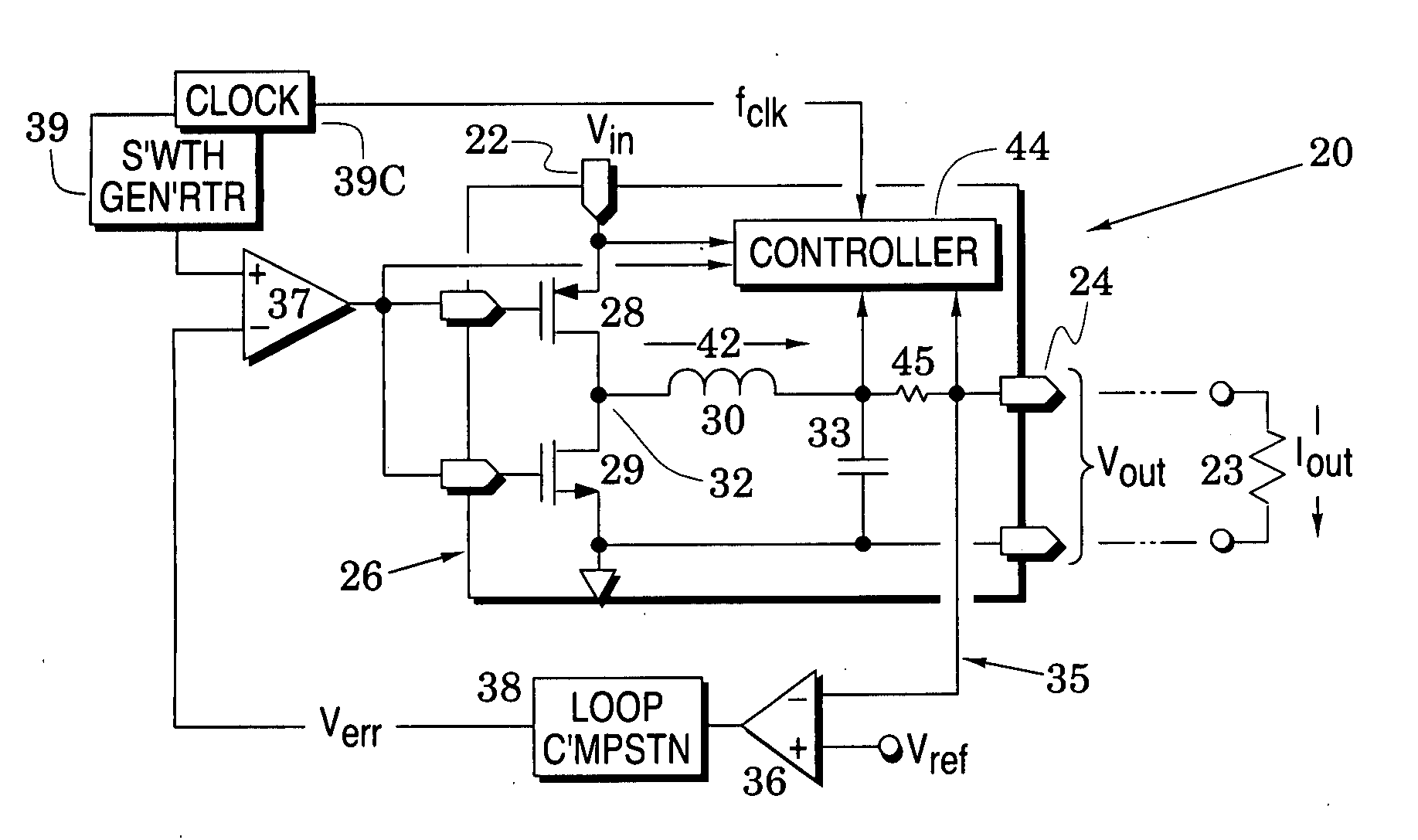
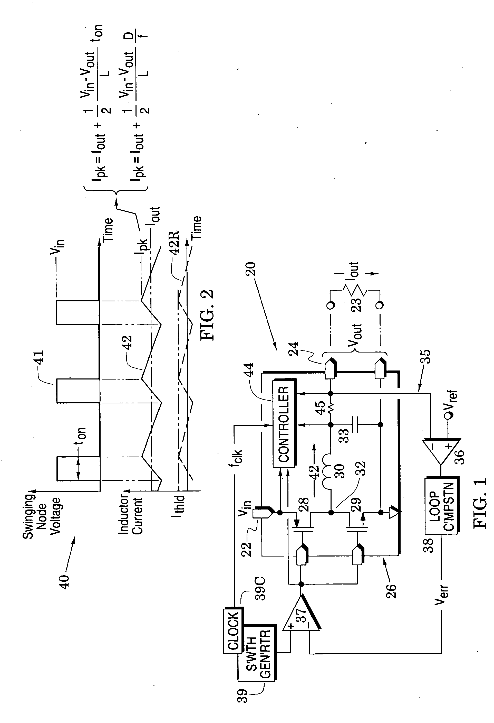
[0015]In particular, FIG. 1 illustrates a switching converter system embodiment 20 that receives an input voltage Vin at an input port 22 and, in response, generates a controlled output voltage Vout across a load 23 at an output port 24 (wherein the load is symbolically indicated by a resistor). The system includes a buck converter 26 that is formed with control and synchronous transistors 28 and 29, an inductor 30, and a load capacitor 33. The sources of the control and synchronous transistors are respectively coupled to the input port 22 and to system ground. The capacitor is coupled across the output port and the inductor is coupled between the capacitor and the drains of the control and synchronous transistors to thereby form a swinging node 32.

[0016]A feedback loop 35 is formed with differential amplifier 36, comparator 37 and loop compensation 38. The differential amplifier 36 and the loop compensation 38 respond to the difference between the output voltage Vout and a referenc...

first embodiment

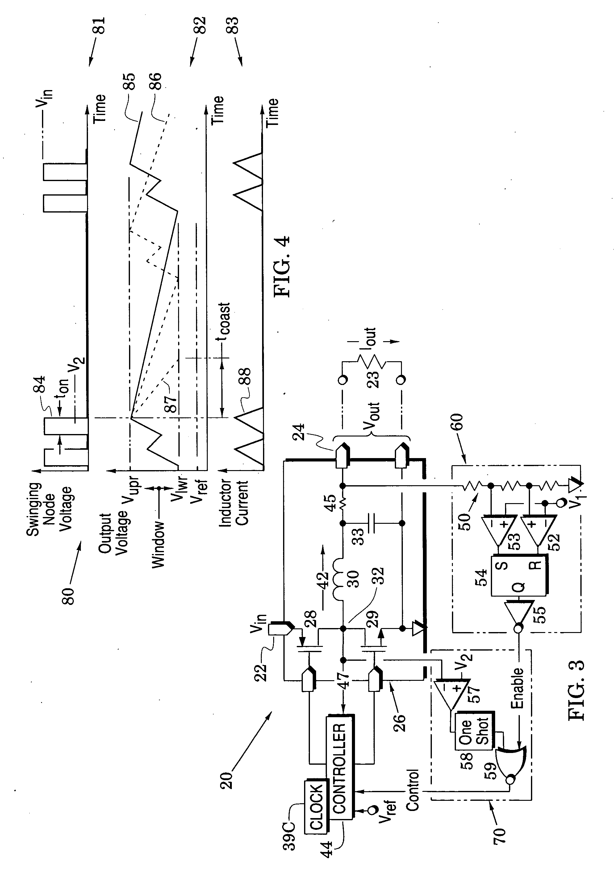
[0031]Before describing FIG. 4, it is noted that FIG. 3 shows that the switching converter system 20 is configured so that the controller 44 can sense when the inductor current 42 has dropped substantially to ground. In a first embodiment, voltages across the small resistor 45 can be provided to the controller 44 so that it receives a reliable measure of the output current Iout. In another embodiment, the controller 44 can monitor the voltage of the swinging node 32 (e.g., with a sense line 47) and compare this voltage to ground. The sense line 47 essentially enables the controller 44 to form a zero-current detector. Yet other embodiments can be used to provide the controller 44 with knowledge of when the inductor current 42 has reached substantially zero.

[0032]FIG. 4 is a graph 80 that illustrates processes in the converter system of FIG. 3 during the PFM operational mode. The graph has a first portion 81 which shows voltages at the swinging node 32 of FIG. 3 and has a second porti...


PUM


Abstract

Efficiently controlled converter system embodiments are provided to operate in different operational modes. In a first operational PWM mode, first and second transistors are switched with a feedback-controlled duty cycle to thereby realize an inductor current that maintains a system output voltage. In a second operational PFM mode, after the output voltage decays to a lower threshold over a decay time, the control and synchronous transistors are driven a sufficient number of times to raise the output voltage to an upper threshold. The systems are controlled to efficiently transition between the first and second operational modes. For example, a converter system preferably transitions to the second PFM operational mode when current peaks of the inductor current drop below a predetermined current threshold and the system preferably transitions to the first PWM operational mode when the output voltage drops to a predetermined reference voltage.

Description

BACKGROUND OF THE INVENTION[0001]1. Field of the invention[0002]The present invention relates generally to switching converters.[0003]2. Description of the Related Art[0004]Switched-mode power supplies (SMPS's) provide superior voltage conversion efficiency because they regulate an output voltage with transistor switches that are either on or off so that they never operate in the linear region in which both current and voltage are nonzero. Because at least one of transistor current and voltage is therefore always close to zero, dissipation is greatly reduced.[0005]Because of their high efficiencies, SMPS's have been found to be particularly useful in a variety of portable devices (e.g., mobile phones, digital cameras, digital radios, portable disk drives and media players) that are powered by internal batteries (e.g., lithium batteries). Although other parameters are also important in these devices, operating efficiency is especially critical as it directly affects battery life. Typ...

Claims


Application Information

Patent Timeline
IPC IPC(8): G05F1/10
CPCH02M3/156Y02B70/16H02M2001/0032H02M1/0032Y02B70/10
Inventor COLLINS, MICHAEL
Owner ANALOG DEVICES INC
Why Eureka
Try Eureka