Display device

Inactive Publication Date: 2010-12-23
MUROI TAKAO +2
View PDF11 Cites 64 Cited by
  • Summary
  • Abstract
  • Description
  • Claims
  • Application Information

AI Technical Summary

Benefits of technology

[0041]According to the present invention, it is possible to provide a display device that can i

Problems solved by technology

However, mercury contained in the discharge tube composes an obstacle for rec

Method used


Image

  • Display device
  • Display device
  • Display device

Examples


Example

Embodiment 1

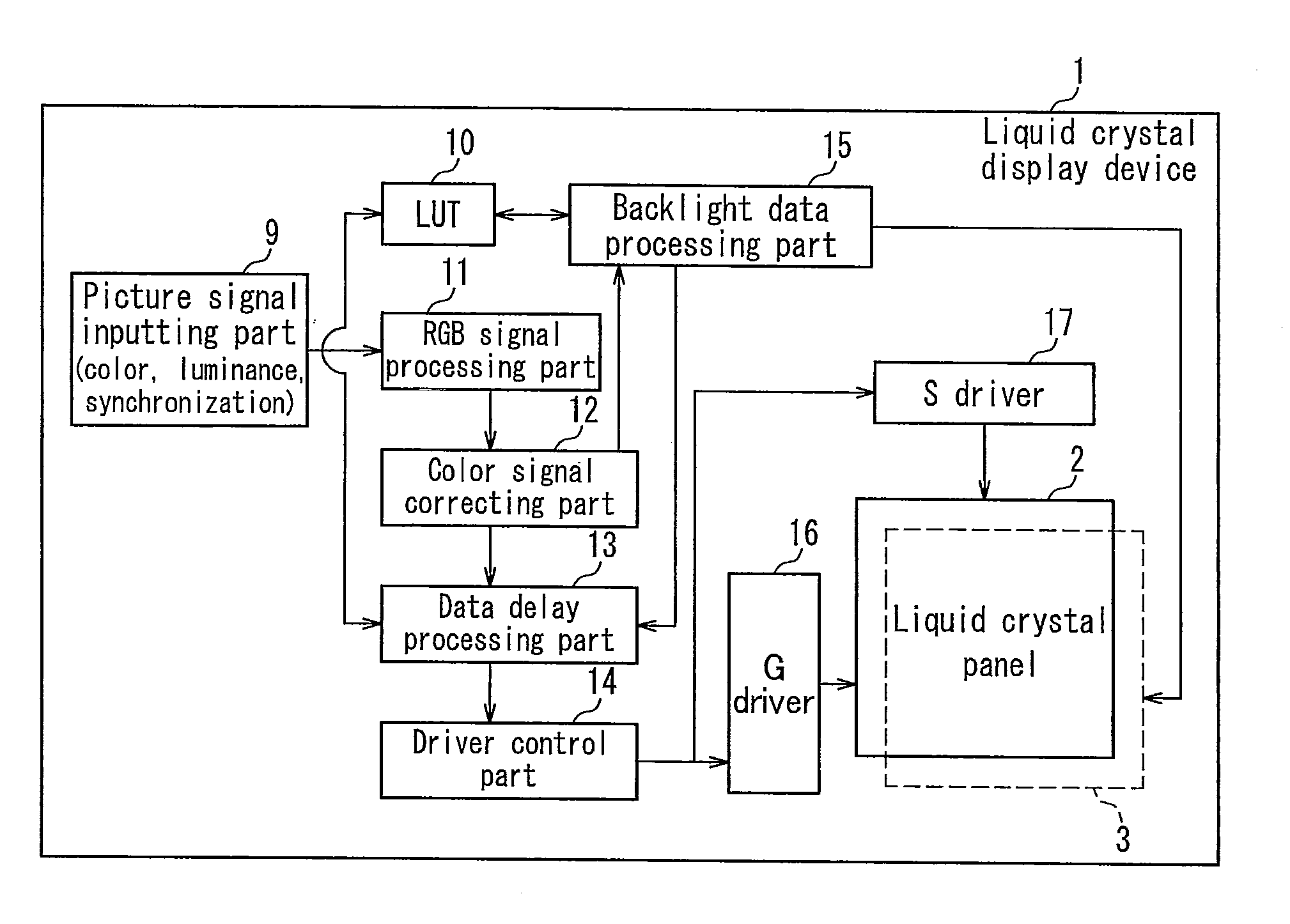
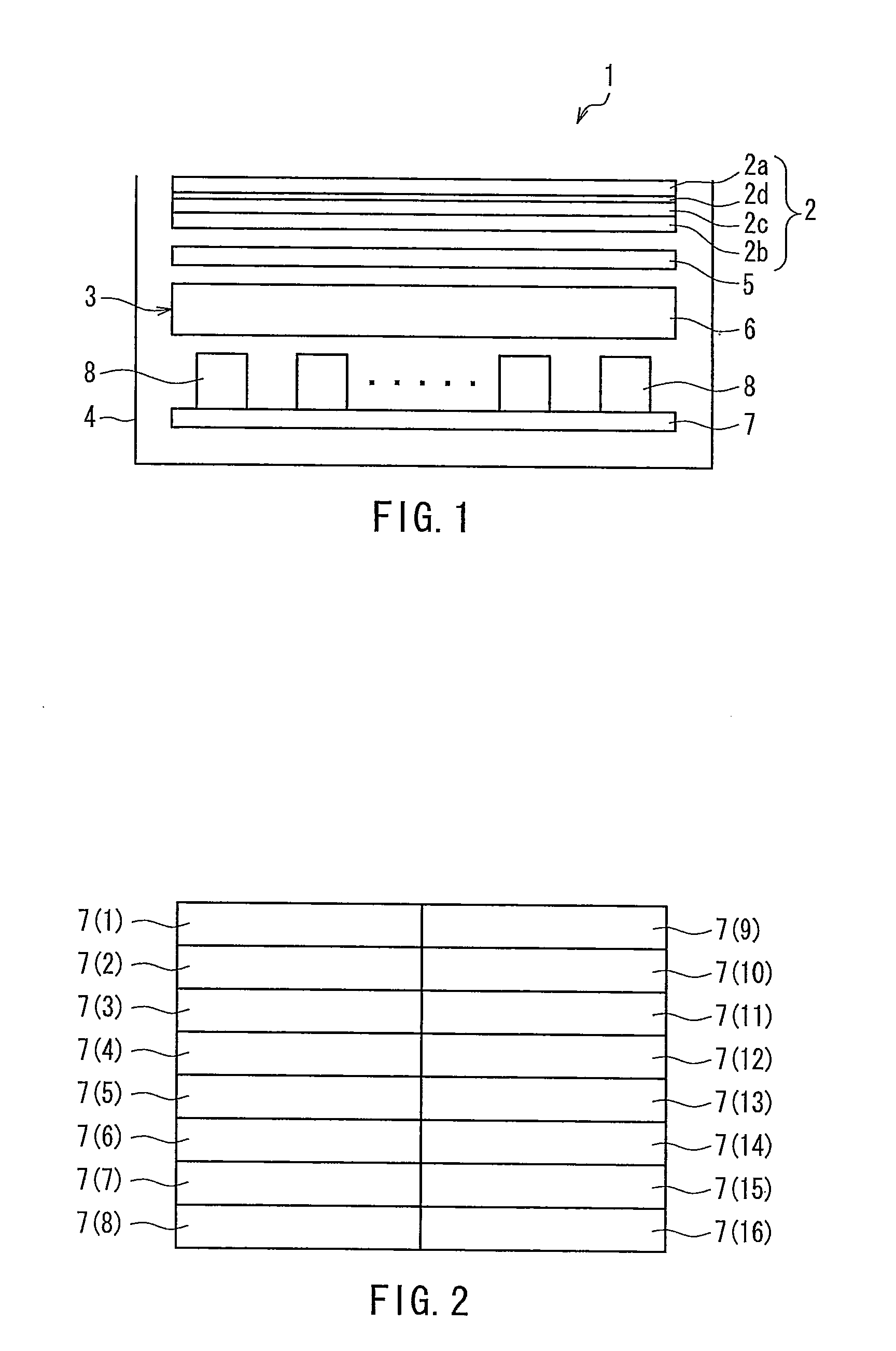
[0061]FIG. 1 is a diagram illustrating a schematic configuration of a liquid crystal display device according to Embodiment 1 of the present invention. In the drawing, a liquid crystal display device 1 of the present embodiment is provided with a liquid crystal panel 2 as a display part to be disposed with its upper surface as the visible side (display surface) and a backlight device 3 as a backlight part that is placed on the non-display surface of the liquid crystal panel 2 (i.e., the lower side in the drawing) and that emits light for illuminating the liquid crystal panel 2. Further in the present embodiment, the liquid crystal panel 2 and the backlight device 3 are contained integrally as a transmission type liquid crystal display device 1 inside a package 4. Further in the liquid crystal display device 1 of the present embodiment, a control part that controls drive of the liquid crystal panel 2 and drive of the backlight device 3 by using a picture signal inputted ...

Example

Embodiment 2

[0161]FIG. 14 is a block diagram showing a configuration of a backlight data processing part in a liquid crystal display device according to Embodiment 2 of the present invention. In this drawing, a main difference between the present embodiment and Embodiment 1 is that the offset computing part compares a determined luminance value of green and a determined luminance value of blue by using the inputted picture signal, and determines the larger luminance value as the luminance value of green and also as the luminance value of blue. In the following description of embodiment, the same reference numerals may be assigned to the same components as those of Embodiment 1 in order to avoid the duplication of explanations.

[0162]Namely, as shown in FIG. 14, in the liquid crystal display device 1 of the present embodiment, an offset computing part 23′ is provided to the backlight controlling part 15. Similarly to the Embodiment 1, the luminance maximal values for the respective c...


PUM


Abstract

It is an object of the present invention to provide a display device that can improve the color reproductivity on a displayed image and improve the display quality. A liquid crystal display device (1) is provided with a backlight device (3) and a liquid crystal panel (2) configured to have capability of color display of information by using illumination light from the backlight device (3). The backlight device (3) has a plurality of illumination areas (Ha) with respect to a plurality of display areas provided on the liquid crystal panel (2), and light-emitting diodes (light sources) of RGB (8r, 8g, 8b) mixable with white light are provided for each illumination area (Ha). Its control part is provided with a backlight control part that determines for each of the light sources a luminance value of light emitted from each of the plural illumination areas (Ha) to a corresponding display area by using an inputted picture signal and that controls the drive of a backlight part, so that an area active backlight drive is carried out. The light-emitting diodes (light sources) of RGB (8r, 8g, 8b) have offset luminances that are set independently from each other.

Description

TECHNICAL FIELD[0001]The present invention relates to a display device, in particular, a non-emission type display device such as a liquid crystal display device.BACKGROUND ART[0002]Recently, for example, a liquid crystal display device has been used widely in a liquid crystal television, a monitor, a mobile telephone and the like, as a flat panel display having advantages such as thinness and light-weight in comparison with conventional Braun tubes. Such a liquid crystal display device includes a backlight device that emits light and a liquid crystal panel that displays a desired image by playing a role as a shutter with respect to light from a light source provided in the backlight device.[0003]The above-described backlight device is classified roughly into a direct-type device an edge-light type device depending on the arrangement of the light source with respect to the liquid crystal panel. In a liquid crystal display device provided with a liquid crystal panel of 20 inches or m...

Claims


Application Information

Patent Timeline
IPC IPC(8): G09G5/10G09G3/36
CPCG09G3/3413G09G3/3426G09G2320/0209G09G2360/16G09G2320/0285G09G2320/0646G09G2320/0666G09G2320/0242
Inventor MUROI, TAKAOFUJIWARA, KOHJIMURAI, TAKAYUKI
Owner MUROI TAKAO
Why Eureka
Try Eureka