Color purity improving sheet, optical apparatus, image display, and liquid crystal display

A technology of color purity and light-emitting devices, applied in optics, optical components, lighting devices, etc., can solve problems such as insufficient filtering of color filters, lack of practicability, and unstable wavelength distribution and spectrum of emitted light.

Inactive Publication Date: 2008-07-30
NITTO DENKO CORP
View PDF3 Cites 13 Cited by
  • Summary
  • Abstract
  • Description
  • Claims
  • Application Information

AI Technical Summary

Problems solved by technology

[0007] However, in a conventional liquid crystal display device, colors between any two of R, G, and B (for example, yellow light of a wavelength band between the R wavelength band and the G wavelength band, and the G wavelength band and the B Light in the wavelength band between the wavelength bands) instead of R, G, and B are mixed in the emission spectrum of the cold cathode tube, and they are not sufficiently filtered out by the color filter
Therefore, there is a problem that color reproducibility deteriorates in display image quality
[0010] However, in the method in which the light guide plate or the light reflector may contain fluorescent substances, there is a problem that fluorescent substances exist in some areas and do not exist in other areas according to their positions in the light guide plate or light emitter, so that the intensity of the emitted light The wavelength distribution spectrum is not constant, which leads to unevenness in color
In addition, in the method of coating a fluorescent substance on, for example, the upper surface of a light guide plate, there is a problem that in-plane unevenness in luminance occurs
In addition, in both methods, the utilization efficiency of light converted with fluorescent substances is not high enough, and the color reproducibility of liquid crystal display devices cannot be considered to be sufficiently high
Moreover, the optical device lacks practicality because, for example, its configuration becomes complicated

Method used


Image

  • Color purity improving sheet, optical apparatus, image display, and liquid crystal display
  • Color purity improving sheet, optical apparatus, image display, and liquid crystal display
  • Color purity improving sheet, optical apparatus, image display, and liquid crystal display

Examples


Embodiment 1

[0075] Manufacture of Color Purity Improved Sheets

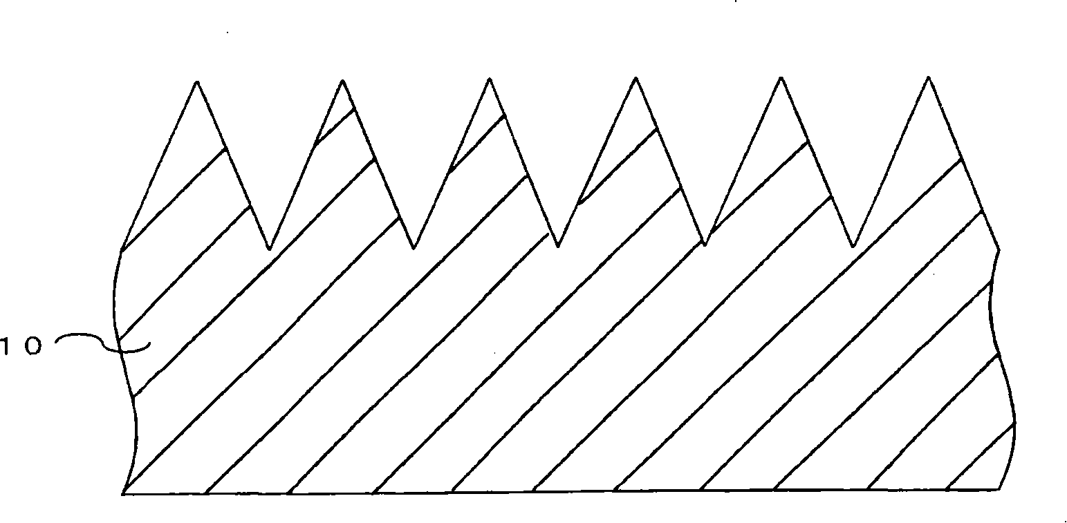
[0076] A fluorescent substance having a structure represented by the above formula (1) (produced by BASF A.G., "LumogenF Red 305" (trade name)) was added and dissolved in a toluene solution of 30% by weight of polymethyl methacrylate to make it It is 0.19 weight% with respect to polymethylmethacrylate. This solution was applied on a polyethylene terephthalate (PET) film substrate with an applicator to form a coating film, and then dried at 80° C. for 30 minutes. Thus a thin film is obtained. After drying, the film was separated from the PET film substrate to obtain a 30 μm thick polymethyl methacrylate film. One surface (light output side surface) of the resulting film was subjected to surface grinding treatment with sandpaper (#100), thus obtaining the color purity improving sheet of this example. The surface on the light output side of the color purity improving sheet had an arithmetic mean surface roughness Ra of 0.8 μ...

Embodiment 2

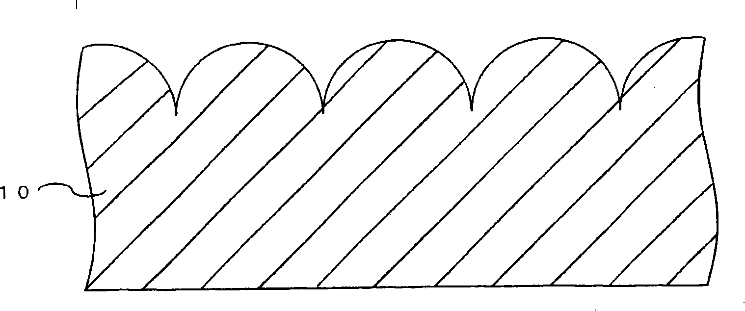
[0078] The color purity improving sheet of this example was obtained in the same manner as in Example 1, except that the surface was ground with sandpaper (#700). The surface on the light output side of the color purity improving sheet had an arithmetic mean surface roughness Ra of 0.13 μm.

Embodiment 3

[0080] The color purity improving sheet of this example was obtained in the same manner as in Example 1, except that the surface was ground with sandpaper (#800). The surface on the light output side of the color purity improving sheet had an arithmetic mean surface roughness Ra of 0.15 μm.


PUM

PropertyMeasurementUnit
surface roughnessaaaaaaaaaa
absorption wavelengthaaaaaaaaaa
surface roughnessaaaaaaaaaa

Abstract

The present invention provides a highly practicable color purity improving sheet that while preventing unevenness in color and brightness from occurring, allows light with an improved color purity to be used for an image display efficiently and can improve color reproducibility of the image display. The color purity improving sheet includes a light-emitting layer which improves the purity of a color in a target wavelength range by absorbing light in a specific wavelength range other than the target wavelength range and converts the absorbed light to emitted light in the target wavelength range. The surface of the light-emitting layer on at least the light outgoing side is roughened so as to have an arithmetic average surface roughness Ra defined in JIS B 0601 (1994 version) in the range of 0.1 to 100 mum.

Description

[0001] Cross References to Related Applications [0002] This application claims priority from Japanese Patent Application No. 2007-14751 filed on January 25, 2007. The entire contents of this Japanese patent application are incorporated herein by reference. technical field [0003] The present invention generally relates to color purity improving sheets, optical devices, image display devices, and liquid crystal display devices. Background technique [0004] Recently, a liquid crystal display device in which light emitted from a light source device such as a cold cathode tube or a light emitting diode (LED) is controlled by a liquid crystal panel and thus forms an image has been developed and put into use. In the liquid crystal display device, in order to uniformly distribute the light emitted by the light source device on the entire display surface, a light guide plate is arranged on the optical path leading to the light source device, and it is parallel to the liquid cry...

Claims


Application Information

Patent Timeline
Patent Type & Authority Applications(China)
IPC IPC(8): G02F1/13357C09K11/00G02F1/1335
CPCG02B5/0278G02B6/0053G02B5/045G02B5/021Y10T428/10G02B6/0051G02B6/0038Y10T428/24364G02F2001/133614G02F2001/133607C09K11/06C09B5/62C09K2211/1029C09K2323/00G02F1/133607G02F1/133614F21S8/085F21S13/10F21W2111/02H02B1/26Y02B20/72
Inventor 长泽德坂本亨枝大谷彰
Owner NITTO DENKO CORP
Why Eureka
Try Eureka