Projection display chip

Inactive Publication Date: 2010-12-23
IND TECH RES INST
View PDF16 Cites 121 Cited by
  • Summary
  • Abstract
  • Description
  • Claims
  • Application Information

AI Technical Summary

Benefits of technology

[0012]The present invention provides a projection display chip, which can integrate light sources of traditional projectors, display devices (such as digital light processor (DLP), liquid crystal on silicon (LCoS) and liquid crystal displayer (LCD)) and optic l

Problems solved by technology

To embed a projector into a device, some technical issues, such as miniaturization, power consumption and manufacturing costs, have to be considered, and of these considerations miniaturization may be the most critical.
The limitations to popularizing micro projectors are the large size, high power consumption, and low light

Method used


Image

  • Projection display chip
  • Projection display chip
  • Projection display chip

Examples


Example

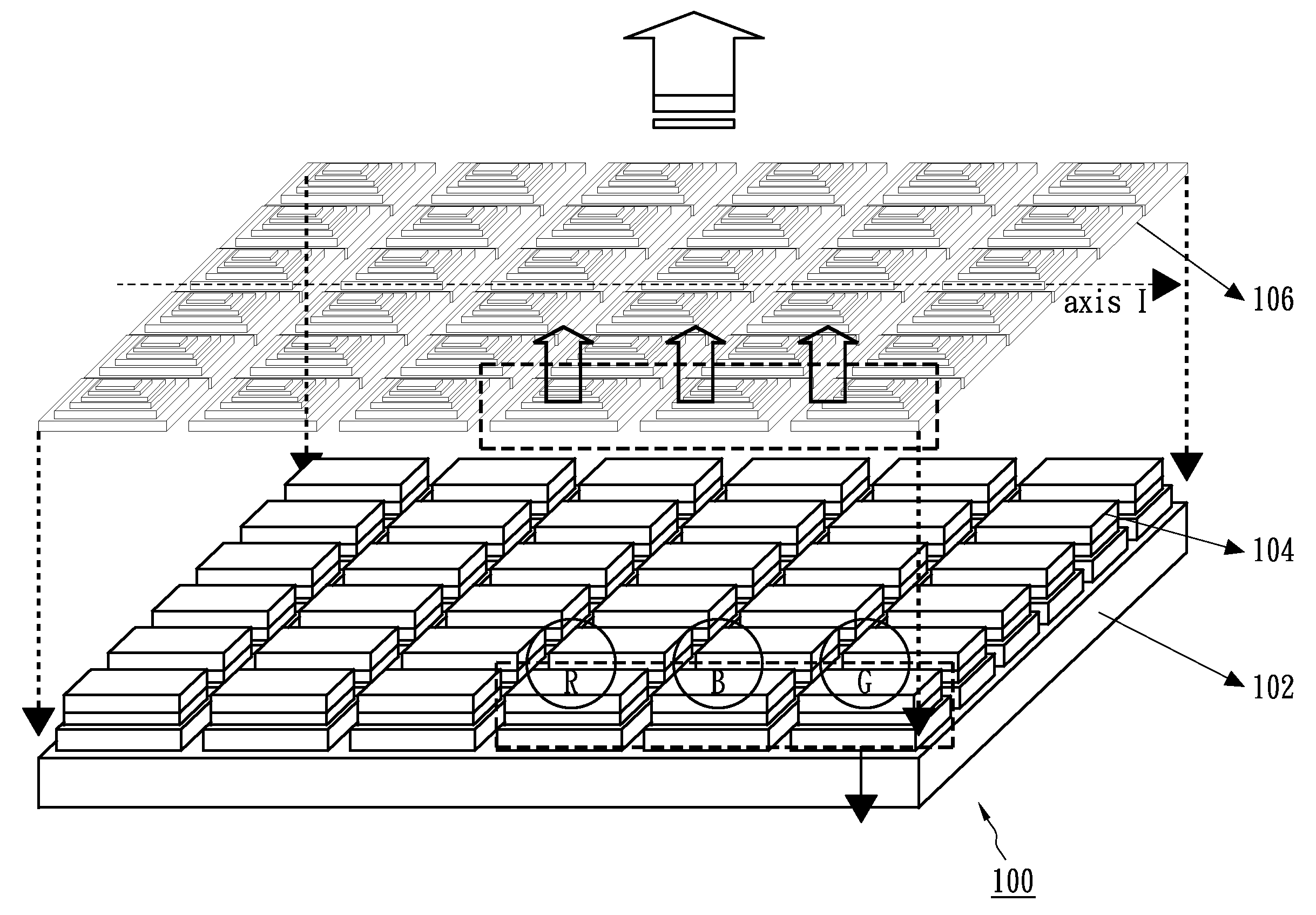
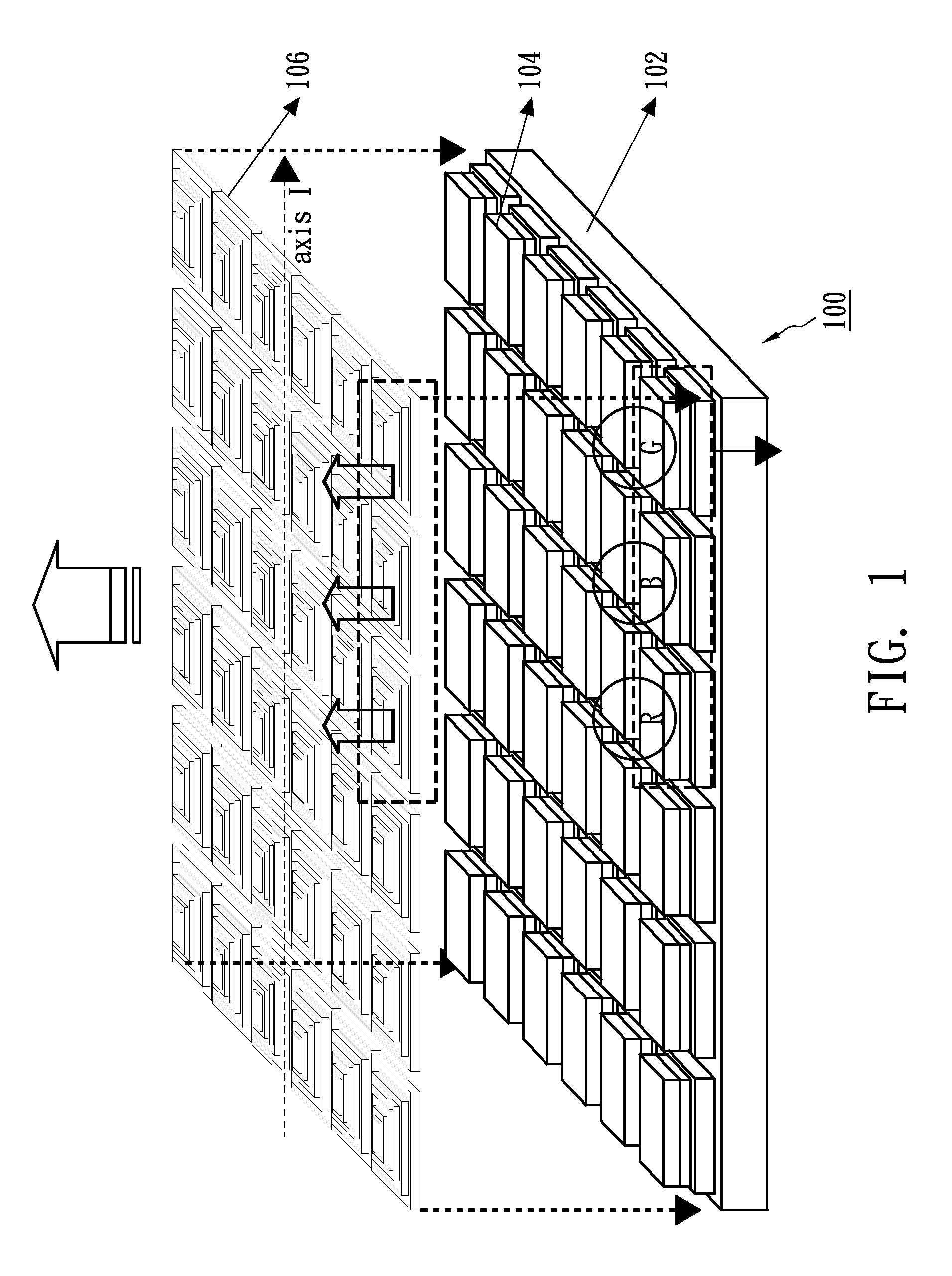
[0027]FIG. 1 shows the architecture of a projection display chip according to an exemplary embodiment. The projection display chip 100 comprises a driving circuit device 102, a micro-LED array 104 and a micro light controlling structure 106. As shown in FIG. 1, the projection display chip 100 integrates a plurality of micro-LEDs into an array in a single chip, wherein the plurality of micro-LEDs comprises red, blue and green LEDs, so as to display images in full color, wherein a pixel of red, blue and green emitter comprises a red LED, a blue LED and a green LED. The driving circuit device 102 drives the micro-LED array 104. The projection display chip 100 also comprises an embedded active addressing control circuit to control the micro-LEDs individually to display images. The micro light controlling structure 106 is formed on or is attached to each micro-LED for focusing and projecting to produce a directional light output. The micro light controlling structure 106 comprises a coll...


PUM


Abstract

A projection display chip comprises a micro light emitting array comprising a plurality of micro LEDs, a micro collimation array comprising a plurality of micro collimation devices, and a projection micro lens array comprising a plurality of micro lenses. Each micro LED has a corresponding driving circuit device. The plurality of micro lenses has different optical axes to enlarge projected images.

Description

CROSS-REFERENCE TO RELATED APPLICATIONS[0001]This application is an application under 35 USC 111(a) and claims priority under 35 USC 119 from Provisional Application Ser. No. 61 / 219,331 filed Jun. 22, 2009 under 35 USC 111(b), entitled “Micro-Light-Emitting Diode (Micro-LED) Projection Chip,” the disclosure of which is incorporated herein by reference.STATEMENT REGARDING FEDERALLY SPONSORED RESEARCH OR DEVELOPMENT[0002]Not applicable.NAMES OF THE PARTIES TO A JOINT RESEARCH AGREEMENT[0003]Not applicable.INCORPORATION-BY-REFERENCE OF MATERIALS SUBMITTED ON A COMPACT DISC[0004]Not applicable.BACKGROUND OF THE INVENTION[0005]1. Field of the Invention[0006]The disclosure relates to a projection display chip.[0007]2. Description of Related Art[0008]Including Information Disclosed Under 37 CFR 1.97 and 37 CFR 1.98.[0009]Micro projectors, also known as pico projectors, mobile projectors or pocket projectors, can be categorized into two types: stand-alone micro projectors or embedded micro ...

Claims


Application Information

Patent Timeline
IPC IPC(8): G03B21/00
CPCG03B21/00G03B21/005
Inventor YEH, WEN YUNGCHUANG, YU HUNGCHAO, CHIA HSINLI, CHIA LINGCHEN, TSE PENG
Owner IND TECH RES INST
Why Eureka
Try Eureka