Centrifugal Impeller and Centrifugal Blower Using It

Active Publication Date: 2010-12-23
PANASONIC CORP
View PDF7 Cites 20 Cited by
  • Summary
  • Abstract
  • Description
  • Claims
  • Application Information

AI Technical Summary

Benefits of technology

[0012]The centrifugal impeller and a centrifugal air blower of the present invention offer high efficiency of air blow and low-noise operations. At the same time, the reduced-size and simplified structure contribute to cost-reduced production.
[0013]The centrifugal impeller of the present invention has a disc-shaped main plate; a plurality of blades; a ring-shaped plate; and a cylindrical wall. The blades are circumferentially disposed on the side of the outer periphery of the front side of the main plate. The ring-shaped plate is attached to tip sections of the blades. The cylindrical wall is disposed on the back side of the main plate so as to be concentric therewith. The structure above provides a centrifugal impeller with improved air-blow efficiency and low-noise operations.
[0014]The centrifugal air blower of the present invention ha

Problems solved by technology

However, the conventional structures of centrifugal impeller 112 and centrifugal air blower 101 disclosed in Patent document 1 have some problems.
This also contributes to degradation of blower efficiency of centrifugal air blowe

Method used


Image

  • Centrifugal Impeller and Centrifugal Blower Using It
  • Centrifugal Impeller and Centrifugal Blower Using It
  • Centrifugal Impeller and Centrifugal Blower Using It

Examples


Example

First Exemplary Embodiment

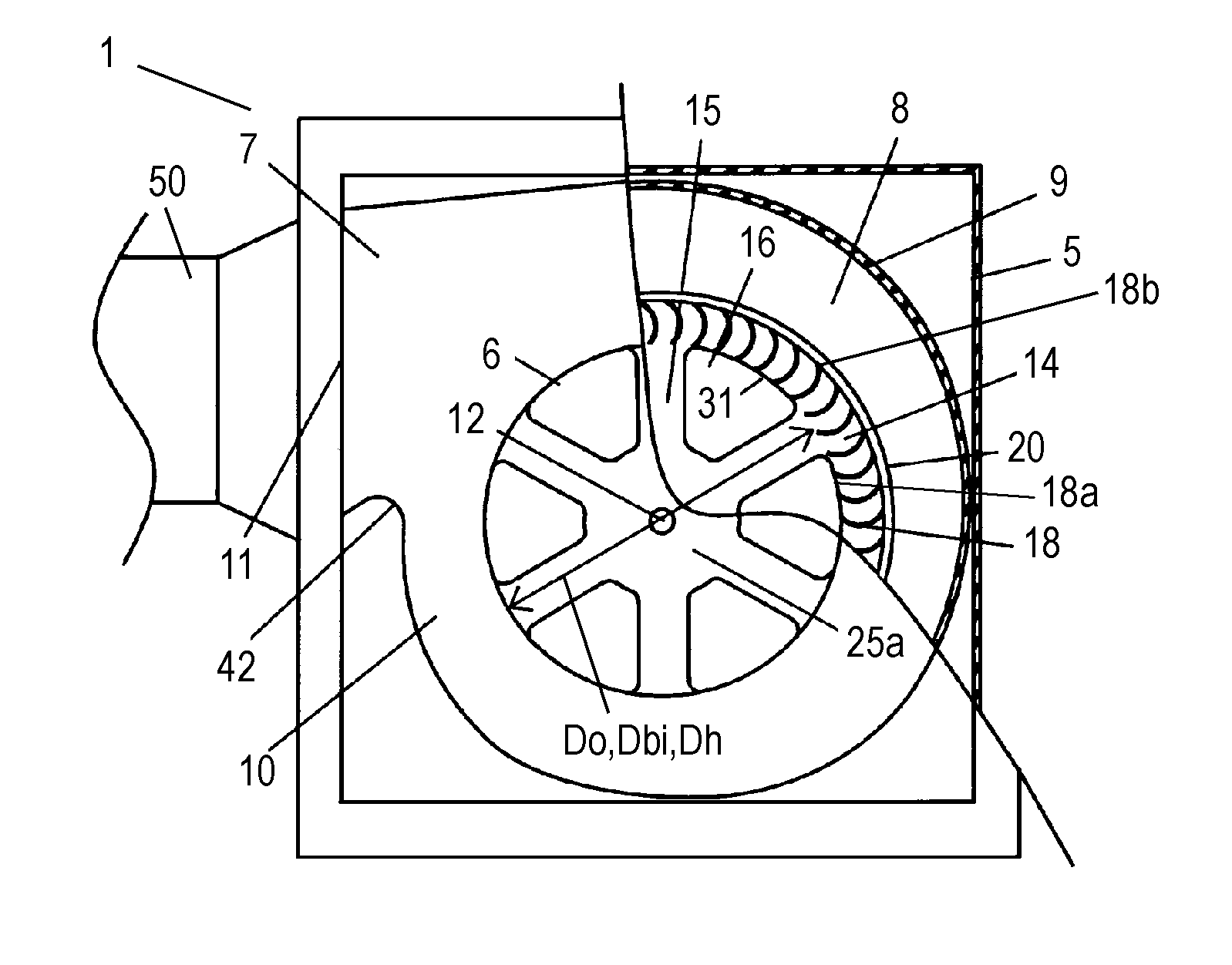
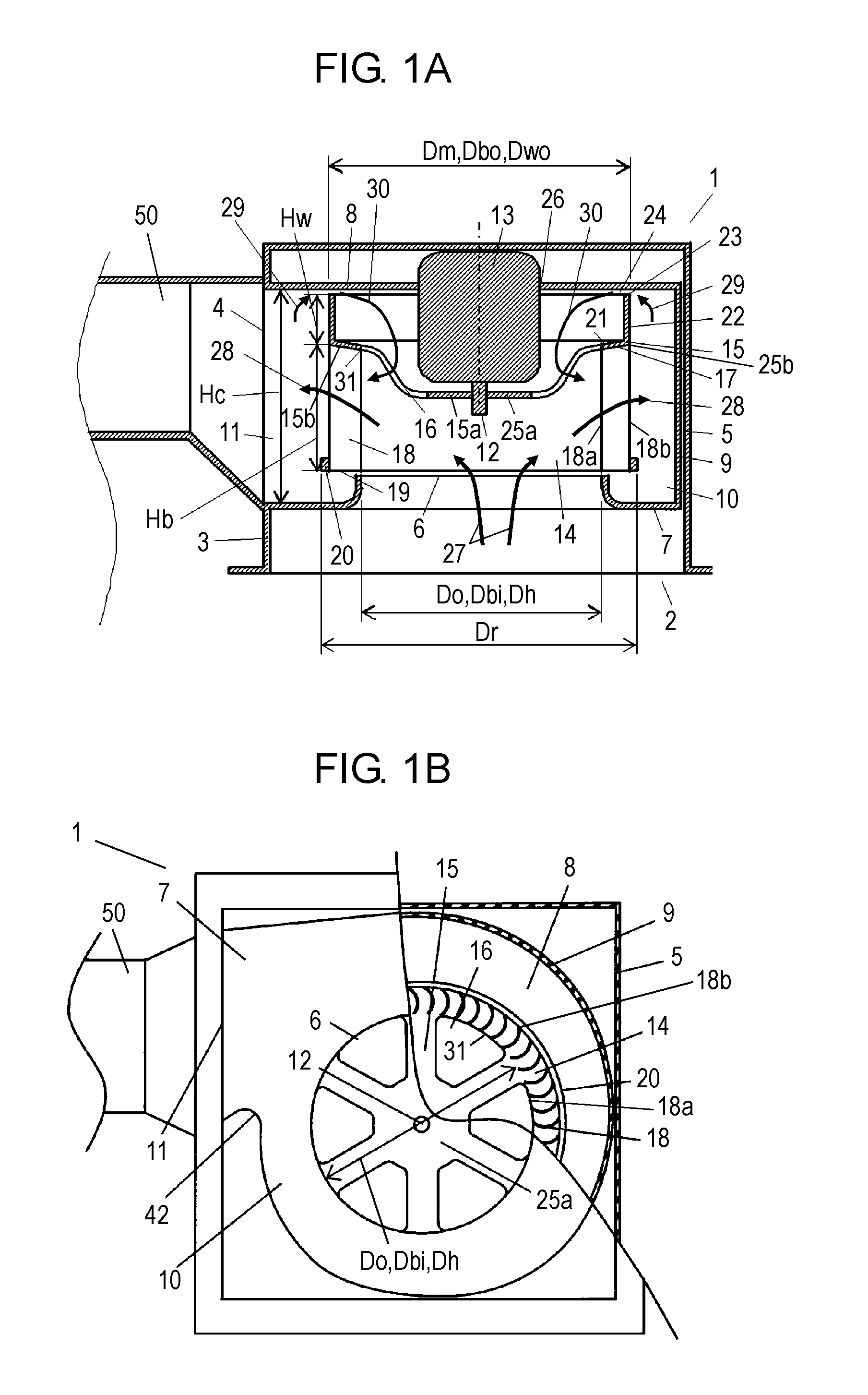
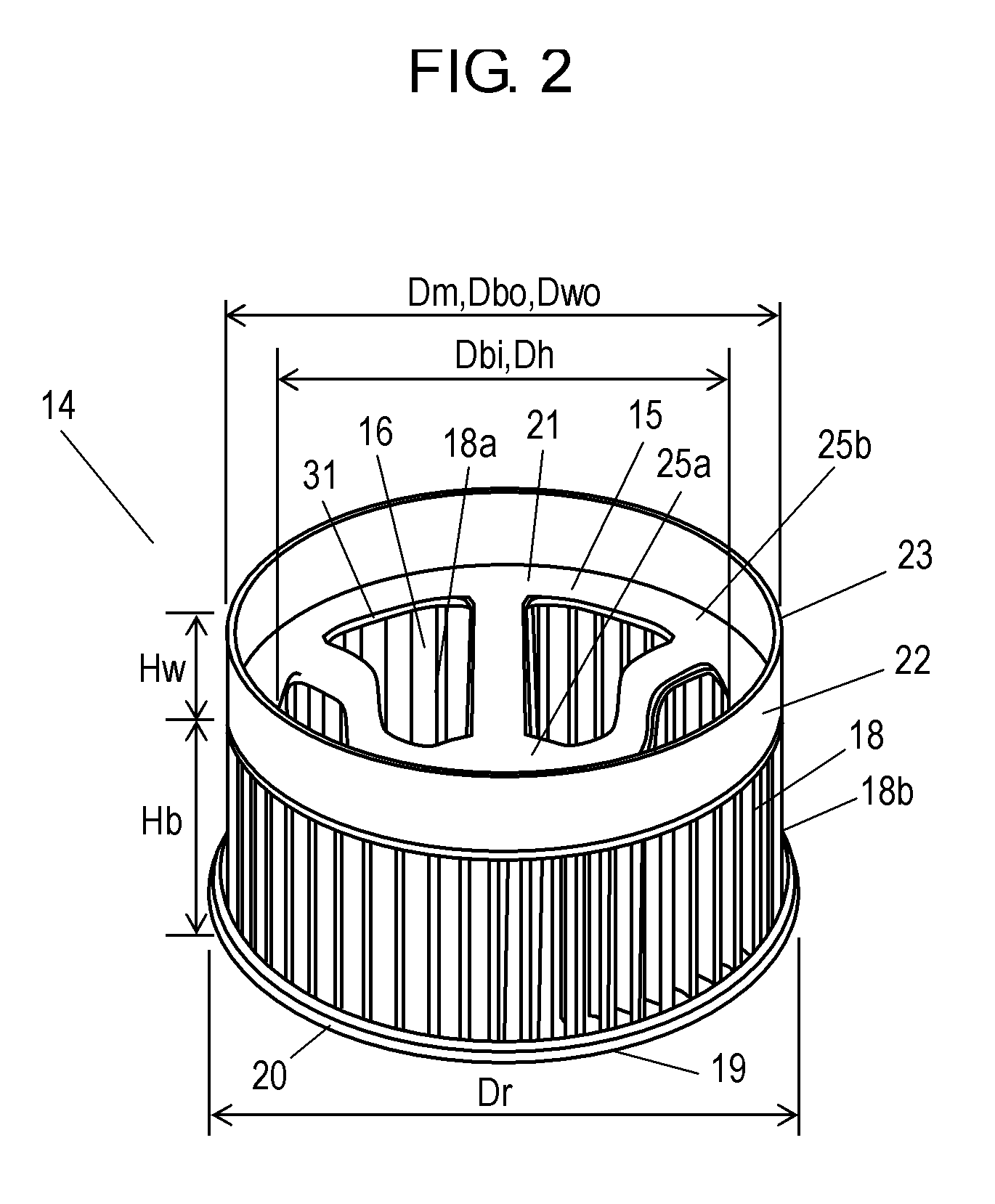
[0086]Here will be described centrifugal impeller 14 and centrifugal air blower 1 of the first exemplary embodiment with reference to FIG. 1 and FIG. 2. Centrifugal air blower 1 (hereinafter referred to as air blower 1) shown in FIGS. 1 and 2 has outer wall 5; casing 10; air outlet 11; electric motor 13; and centrifugal impeller 14 (hereinafter, impeller 14). Outer wall 5 has bottom 2 as an opening and side 3 in which duct-connection opening 4 (hereinafter, opening 4) is formed. Outer wall 5 measures 258 mm square and 198 mm in height. Casing 10 is formed of air-intake plate 7, back plate 8, and side wall 9, which are disposed inside outer wall 5, in a manner that side wall 9 is held between air-intake plate 7 and back plate 8. Air-intake plate 7 has bell-mouthed air inlet 6 with inner diameter Do of 148 mm. Back plate 8 has a flat shape and faces air-intake plate 7. Side wall 9 has a spiral shape and has height Hc of 107 mm. Air outlet 11, which is dispose...

Example

Second Exemplary Embodiment

[0108]FIGS. 4A and 4B show centrifugal impeller 14 and centrifugal air blower 1 of the second exemplary embodiment. In the drawings, the same reference marks are used as in the structure described in the first embodiment for similar parts and in-detail explanations thereof will be omitted. According to the centrifugal air blower 1 of the embodiment, as shown in FIGS. 4A and 4B, cylindrical wall 22 disposed on back side 21 has a double-walled structure formed of outer cylindrical wall 32 (hereinafter, wall 32) and inner cylindrical wall 33 (hereinafter, wall 33). Wall 32 forms the outer periphery of cylindrical wall 22 and has outer diameter Dwo of 182 mm. Wall 33 forms the inner periphery of cylindrical wall 22 and has inner diameter Dwi of 145 mm that is equal to outer diameter Dh of ventilation holes 16. Wall 33 has a thickness of 2 mm. Edge 23 of wall 33 is flush with edge 23 of wall 32. Wall 32 and wall 33 form cylindrical space 36 (hereinafter, space ...

Example

Third Exemplary Embodiment

[0113]FIG. 5 shows centrifugal impeller 14 and centrifugal air blower 1 in accordance with the third exemplary embodiment of the present invention. In the drawing, the same reference marks are used as in the structure described in the first and the second embodiments for similar parts and in-detail explanations thereof will be omitted. According to centrifugal air blower 1 of the embodiment, as shown in FIG. 5, cylindrical wall 22 is formed of sound-absorbing material 35, such as rigid polyurethane foam. Sound-absorbing material 35 absorbs noise generated in the periphery of impeller 14, decreasing noise generated in air blower 1 and impeller 14.


PUM


Abstract

Centrifugal impeller (14) of centrifugal air blower (1) has main plate (15); a plurality of blades (18); ring-shaped plate (20); and a cylindrical wall (22). The blades (18) are circumferentially disposed on the side of the outer periphery of front side (17) of main plate (15). Ring-shaped plate (20) is attached to tip sections (19) of blades (18). Cylindrical wall (22) is disposed on the back side (21) of the main plate (15) so as to be concentric therewith. The structure above provides centrifugal impeller (14) and centrifugal air blower (1) with improved air-blow efficiency and noise-reduced operations.

Description

TECHNICAL FIELD[0001]The present invention relates to a centrifugal impeller used for a ventilating fan and an air-conditioning device, and also relates to a centrifugal air blower using the centrifugal impeller.BACKGROUND ART[0002]In recent years, there has been an increasing need for a downsized structure of a ventilating fan and an air-conditioning device so as to be suitable for a limited installation space in a living or non-living environment. At the same time, there has been a growing demand for the devices to have improved air-blow efficiency and noise-reduced structure.[0003]Hereinafter will be described conventional structures of a centrifugal impeller and a centrifugal air blower with reference to FIG. 14. Centrifugal air blower 101 of FIG. 14 has casing 107; centrifugal impeller 112 with a multi-blade structure; and electric motor 113. Casing 107 has air-intake plate 103; back plate 104 that faces air-intake plate 103; and side wall 106. Casing 107 is formed so that air-...

Claims


Application Information

Patent Timeline
IPC IPC(8): F04D29/44F04D29/38
CPCF04D29/282
Inventor SHIRAHAMA, SEIJIYOSHIKAWA, HITOSHI
Owner PANASONIC CORP
Why Eureka
Try Eureka