Micropump structure

a micro-pump and structure technology, applied in the direction of positive displacement liquid engines, piston pumps, liquid fuel engines, etc., can solve the problems of difficult application of micro-pump b>3/b> to a site with a smaller room, poor tightness, and easy liquid leakage, etc., to achieve improved micro-pump structure, enhanced working efficiency, and greatly reduced axial height

Active Publication Date: 2010-12-23
ASIA VITAL COMPONENTS SHENZHEN CO LTD
View PDF12 Cites 10 Cited by
  • Summary
  • Abstract
  • Description
  • Claims
  • Application Information

AI Technical Summary

Benefits of technology

[0003]A primary object of the present invention is to provide an improved micropump structure with greatly reduced axial height and enhanced working efficiency.
[0004]A further object of the present invention is to provide the above micropump structure, which has better tightness.

Problems solved by technology

Such structure has so many junctures that the tightness is relatively poor.
As a result, leakage of the liquid is apt to take place.
This makes it difficult to apply the micropump 3 to a site with smaller room.
1. The conventional micropump has higher axial height.
2. The application range of the conventional micropump is narrow.
3. The conventional micropump has poor leakproofness.

Method used


Image

  • Micropump structure
  • Micropump structure
  • Micropump structure

Examples


Embodiment Construction

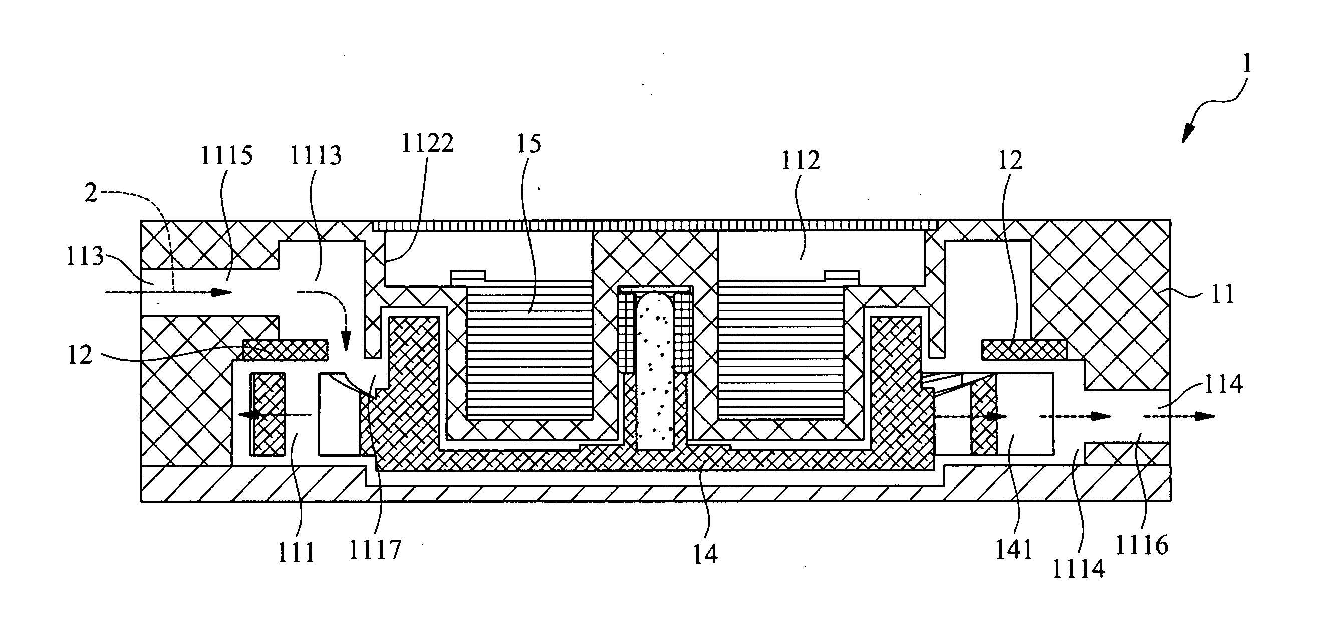
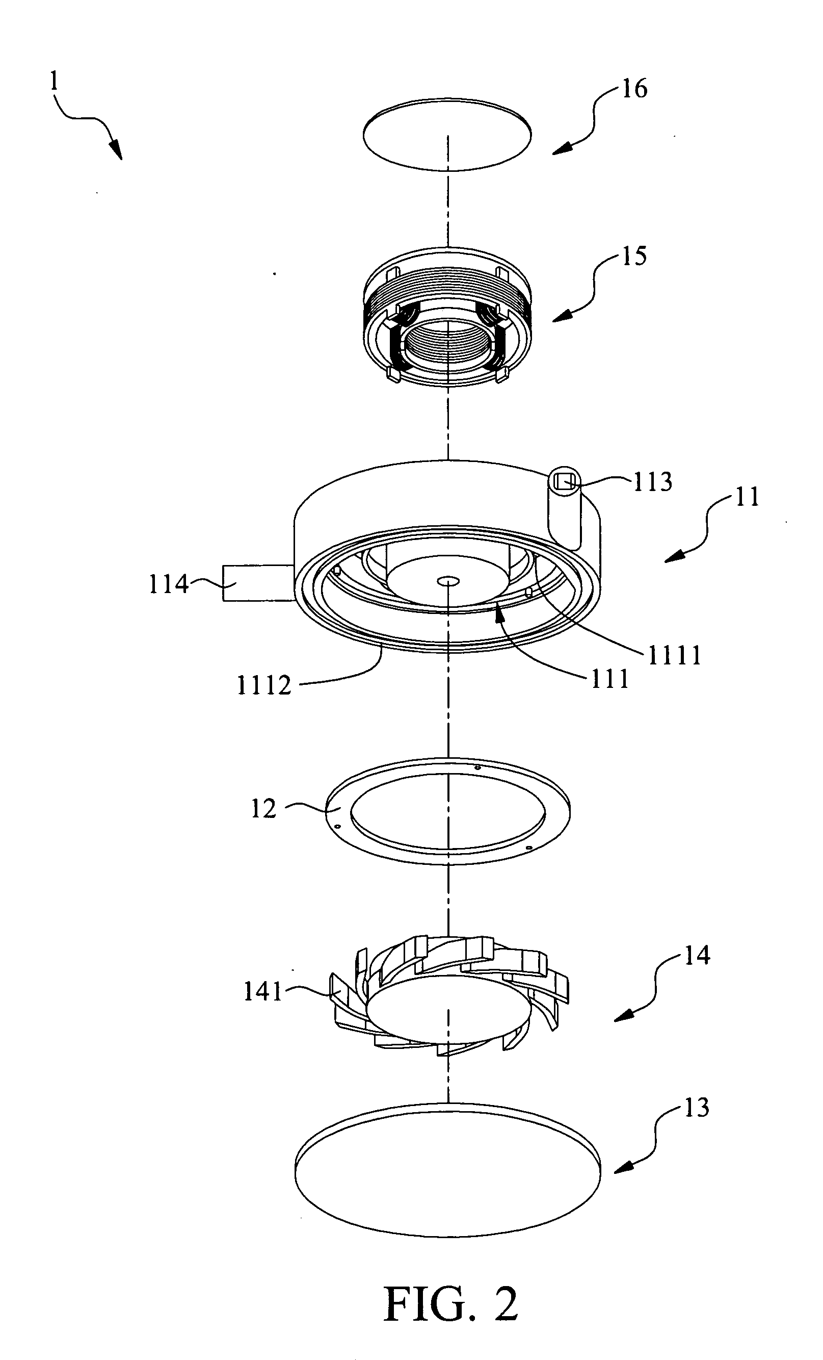
[0012]Please refer to FIGS. 2, 3 and 4, in which FIG. 2 is a perspective exploded view of the present invention, FIG. 3 is a perspective assembled view of the present invention and FIG. 4 is a sectional assembled view of the present invention. The micropump structure 1 of the present invention includes a main body 11, at least one water room partitioning board 12, at least one fan propeller 14 and at least one drive unit 15. In this embodiment, the drive unit 15 is a motor. The main body 11 has at least one water room 111, a drive unit receiving space 112, an inlet 113 and an outlet 114. The water room 111 and the drive unit receiving space 112 are respectively disposed at two ends of the main body 11. The inlet 113 and the outlet 114 are disposed on a circumference of the main body 11 in communication with the water room 111. Referring to FIG. 4, the water room partitioning board 12 is disposed in the water room 111 to divide the water room 111 into at least one water incoming sect...


PUM


Abstract

A micropump structure including a main body, at least one water room partitioning board, at least one fan propeller and at least one drive unit. The main body has at least one water room, an inlet and an outlet. The inlet and the outlet are disposed on a circumference of the main body in communication with the water room. The water room partitioning board is disposed in the water room to divide the water room into at least one water incoming section and at least one water discharging section. The fan propeller is disposed in the water room. The drive unit is disposed in the main body. By means of the water room partitioning board, the flow guiding efficiency of the micropump is greatly enhanced and the axial height of the micropump is reduced so that the working efficiency is promoted and less room is occupied.

Description

FIELD OF THE INVENTION[0001]The present invention relates to an improved micropump structure with greatly reduced axial height and enhanced working efficiency.BACKGROUND OF THE INVENTION[0002]Please refer to FIG. 1, which is a sectional assembled view of a conventional micropump. The conventional micropump 3 is mounted in a liquid reservoir 5 in which a cooling liquid 4 is contained. The micropump 3 includes a casing 315 a top sealing cover 32, a fan 33 and a bottom sealing cover 34. The casing 31 and the top sealing cover 32 together define a flow space 35 in which the fan 33 is accommodated. The top sealing cover 32 has a liquid inlet 351 and a liquid outlet 352. The bottom sealing cover 34 has a bottom face 341 formed with a guide groove 342. A water outlet 343 and an exhaust port 344 are formed in the guide groove 342 at an interval in communication with the flow space 35. The water outlet 343 has a diameter slightly larger than that of the exhaust port 344. One end of the guide...

Claims


Application Information

Patent Timeline
Patent Type & Authority Applications(United States)
IPC IPC(8): F04D13/06F04D29/42
CPCF04D13/08F04D29/605F04D29/406F04D13/06F04D13/0606F04D29/426
Inventor TANG, SAM
Owner ASIA VITAL COMPONENTS SHENZHEN CO LTD
Why Eureka
Try Eureka