
Apparatus and Method for Providing Resist Alignment Marks in a Double Patterning Lithographic Process

Inactive Publication Date: 2010-12-23
ASML NETHERLANDS BV
View PDF1 Cites 6 Cited by
  • Summary
  • Abstract
  • Description
  • Claims
  • Application Information

AI Technical Summary

Benefits of technology

[0009]In one embodiment of the present invention, a method of semiconductor manufacturing using a double patterning process is provided. The method includes coating a substrate with a first resist-layer, followed by exposing and developing the first resist layer to form the first pattern including one or more alignment marks. After freezing the first resist layer, the first resist layer is planarized by coating the first lithography pattern with a second resist layer. By soft baking the second resist layer, the shrinkage effects of the second resist layer can be exploited to provide alignment mark topography based on the one or more alignment marks in the first resist layer. Such alignment mark topography can then be used to support the generation of alignment signals with little alignment error.
[0011]The present invention also relates to an article of manufacture including: a substrate coated with a first resist layer; one or more alignment marks formed in the first resist layer; and a second resist layer coating the first resist layer. The first resist layer is planarized by coating the first lithography pattern with a second resist layer. By soft baking the second resist layer, the shrinkage effects of the second resist layer can be exploited to provide alignment mark topography on the article of manufacture based on the one or more first alignment marks. Such alignment mark topography can then be used to support the generation of alignment signals with little alignment error in the subsequent double patterning processing of the article of manufacture.

Problems solved by technology

Using LELE or LFLE, there exists the potential for error in the placement of features during the second lithography step with respect to the features from the first lithography step.

Method used


Image

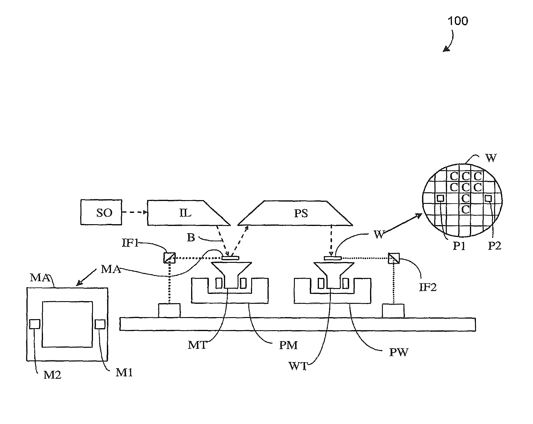
  • Apparatus and Method for Providing Resist Alignment Marks in a Double Patterning Lithographic Process
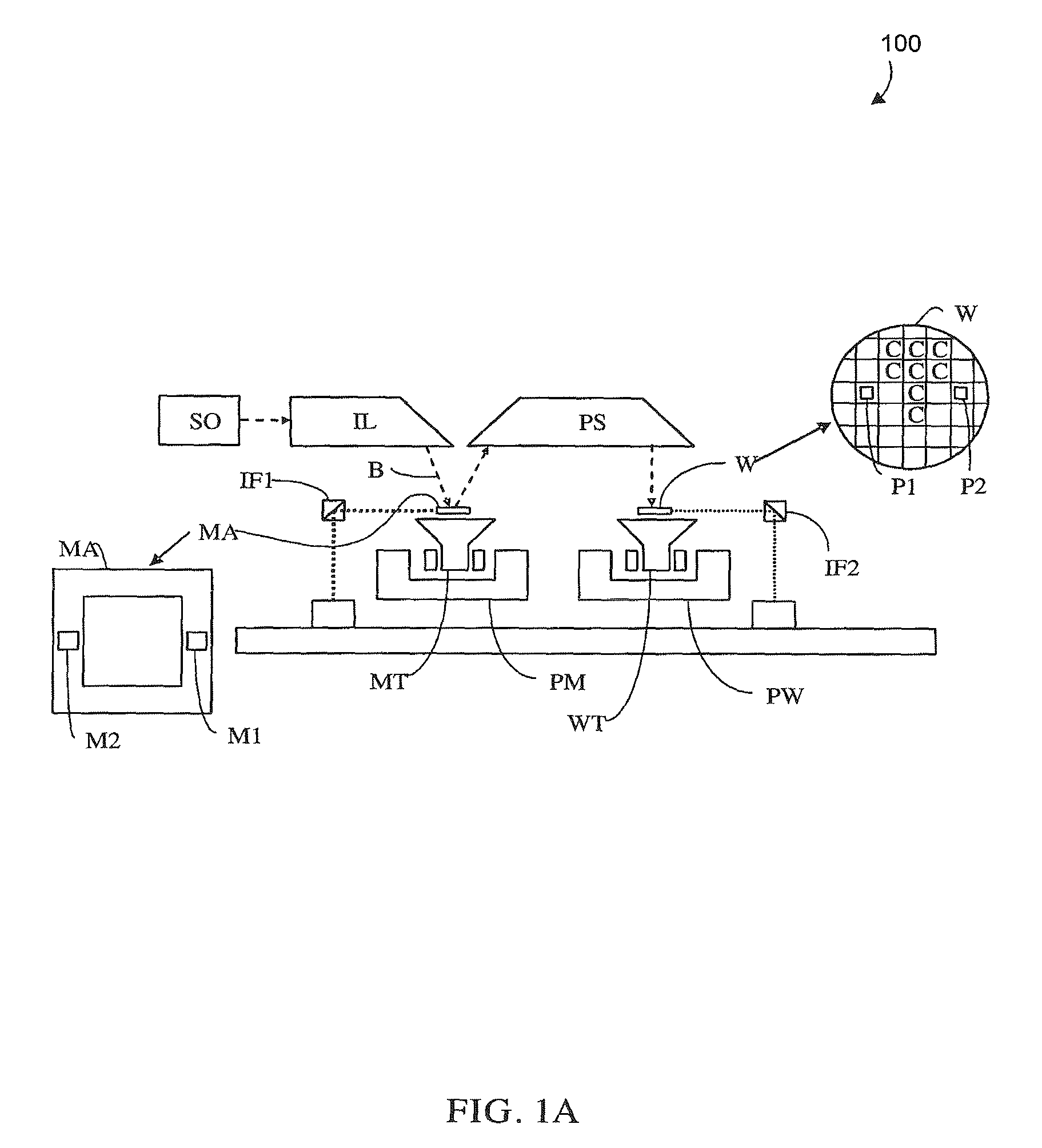
  • Apparatus and Method for Providing Resist Alignment Marks in a Double Patterning Lithographic Process
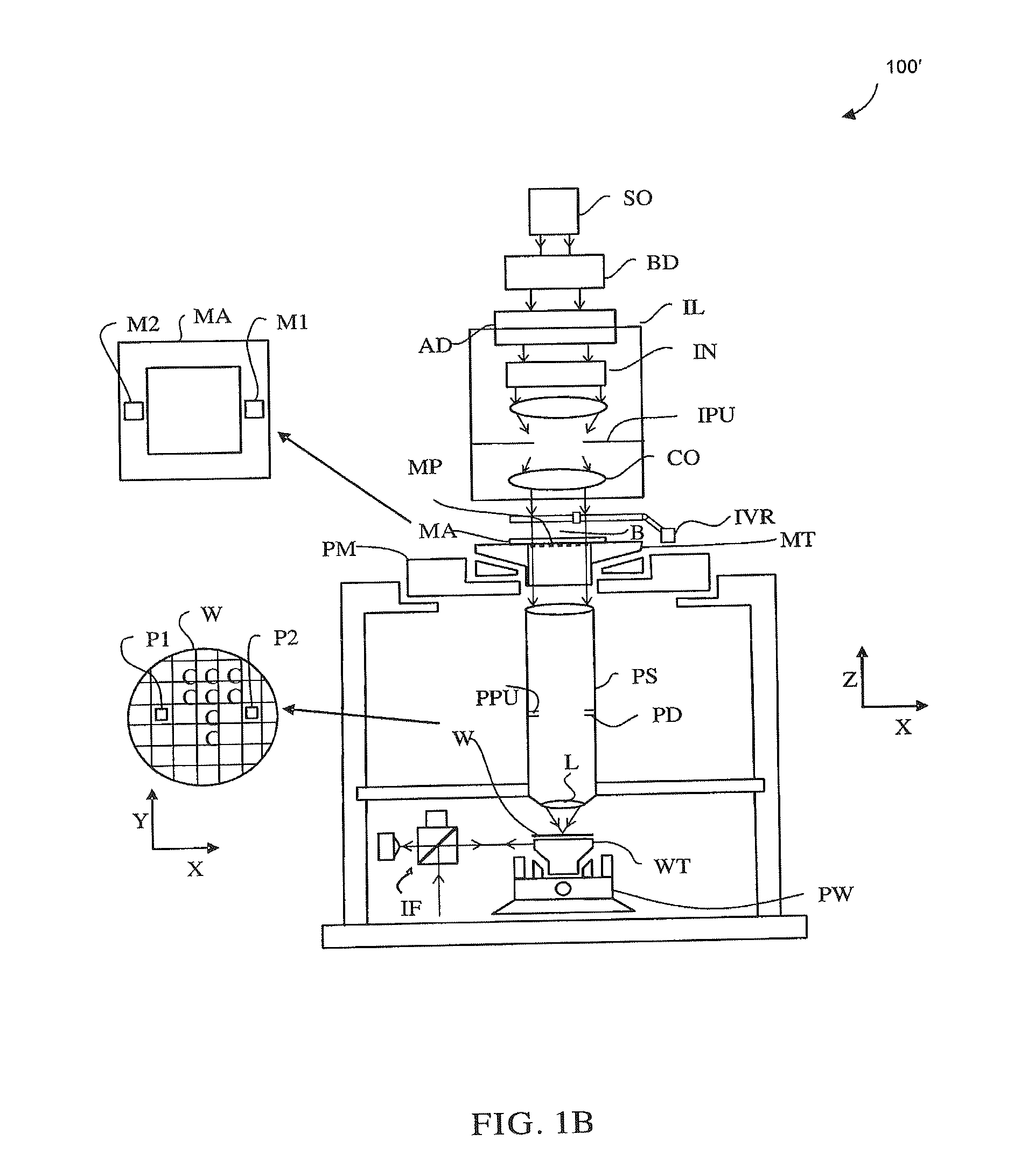
  • Apparatus and Method for Providing Resist Alignment Marks in a Double Patterning Lithographic Process

Examples


Embodiment Construction

[0025]This specification discloses one or more embodiments that incorporate the features of this invention. The disclosed embodiment(s) merely exemplify the invention. The scope of the invention is not limited to the disclosed embodiment(s). The invention is defined by the claims appended hereto.

[0026]The embodiment(s) described, and references in the specification to “one embodiment”, “an embodiment”, “an example embodiment”, etc., indicate that the embodiment(s) described may include a particular feature, structure, or characteristic, but every embodiment may not necessarily include the particular feature, structure, or characteristic. Moreover, such phrases are not necessarily referring to the same embodiment. Further, when a particular feature, structure, or characteristic is described in connection with an embodiment, it is understood that it is within the knowledge of one skilled in the art to effect such feature, structure, or characteristic in connection with other embodimen...


PUM

PropertyMeasurementUnit
Thicknessaaaaaaaaaa
Symmetric field theoryaaaaaaaaaa

Abstract

A method is described for alignment of a substrate during a double patterning process. A first resist layer containing at least one alignment mark is formed on the substrate. After the first resist layer is developed, a second resist layer is deposited over the first resist layer, leaving a planar top surface (i.e., without topography). By baking the second resist layer appropriately, a symmetric alignment mark is formed in the second resist layer with little or no offset error from the alignment mark in the first resist layer. The symmetry of the alignment mark formed in the second resist can be enhanced by appropriate adjustments of the respective thicknesses of the first and second resist layers, the coating process parameters, and the baking process parameters.

Description

CROSS REFERENCE TO RELATED APPLICATIONS[0001]This patent application claims the benefit of U.S. Provisional Patent Application No. 61 / 182,411 filed on May 29, 2009, entitled “Apparatus And Method For Providing Resist Alignment Marks In A Double Patterning Lithographic Process”, which is incorporated by reference herein in its entirety.BACKGROUND OF THE INVENTION[0002]1. Field of the Invention[0003]Embodiments of the present invention relate generally to lithography, and more particularly to improving alignment targets in lithographic patterning processes, such as a double patterning process.[0004]2. Background Art[0005]A lithographic apparatus is a machine that applies a desired pattern onto a substrate, usually onto a target portion of the substrate. A lithographic apparatus can be used, for example, in the manufacture of integrated circuits (ICs). In that instance, a patterning device, which is alternatively referred to as a mask or a reticle, may be used to generate a circuit pat...

Claims


Application Information

Patent Timeline
IPC IPC(8): B32B3/10G03F7/20G03B27/42
CPCG03F7/0035G03F7/40G03F7/70466G03F9/7065Y10T428/24851G03F9/7084H01L21/0273Y10T428/24802G03F9/708H01L21/0274
Inventor DOYTCHEVA, MAYA ANGELOVADUSA, MIRCEAVAN HAREN, RICHARD JOHANNES FRANCISCUSSEWELL, HARRYVAN DER HEIJDEN, ROBERTUS WILHELMUS
Owner ASML NETHERLANDS BV
Learn More