Electric power steering system

a technology of steering system and electric motor, which is applied in the direction of steering initiation, instruments, vessel construction, etc., can solve the problems of large output change, less noise, and driver's uncomfortable steering feel, and achieve the effect of suppressing sharp changes in output transition coefficien

Active Publication Date: 2010-12-23
JTEKT CORP
View PDF10 Cites 6 Cited by
  • Summary
  • Abstract
  • Description
  • Claims
  • Application Information

AI Technical Summary

Benefits of technology

[0012]In the configuration described above, the frequency band of the transition coefficient is lower than the frequency band of the compensation component. Accordingly, it is

Problems solved by technology

The driver tends to have an uncomfortable steering feel especially during the transition of the steering states.
As a result, a slight change in the steering speed may cause a great change in the output.
Thus, the

Method used


Image

  • Electric power steering system
  • Electric power steering system
  • Electric power steering system

Examples


first embodiment

[0027]Hereafter, the invention will be described with reference to the accompanying drawings.

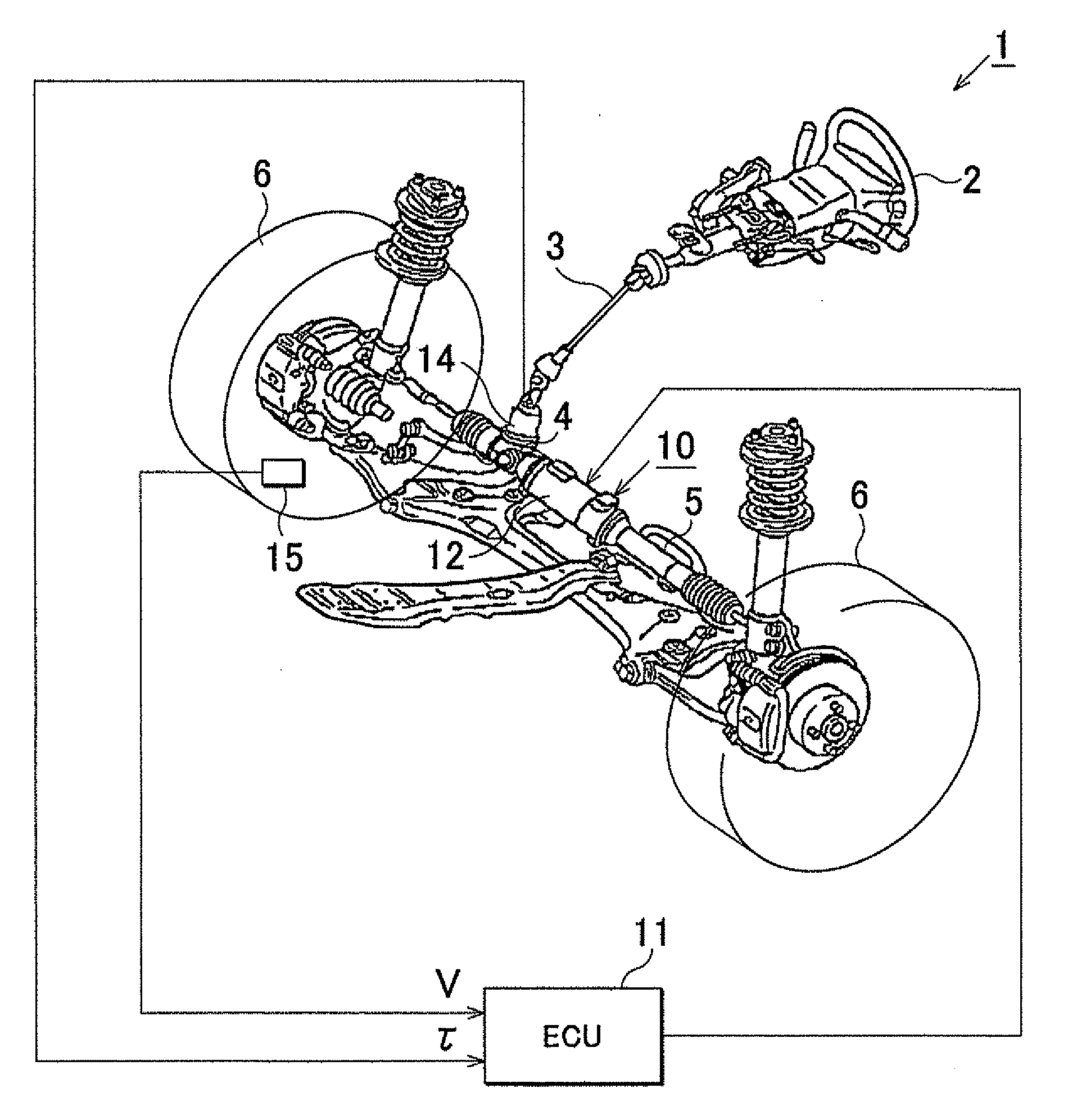
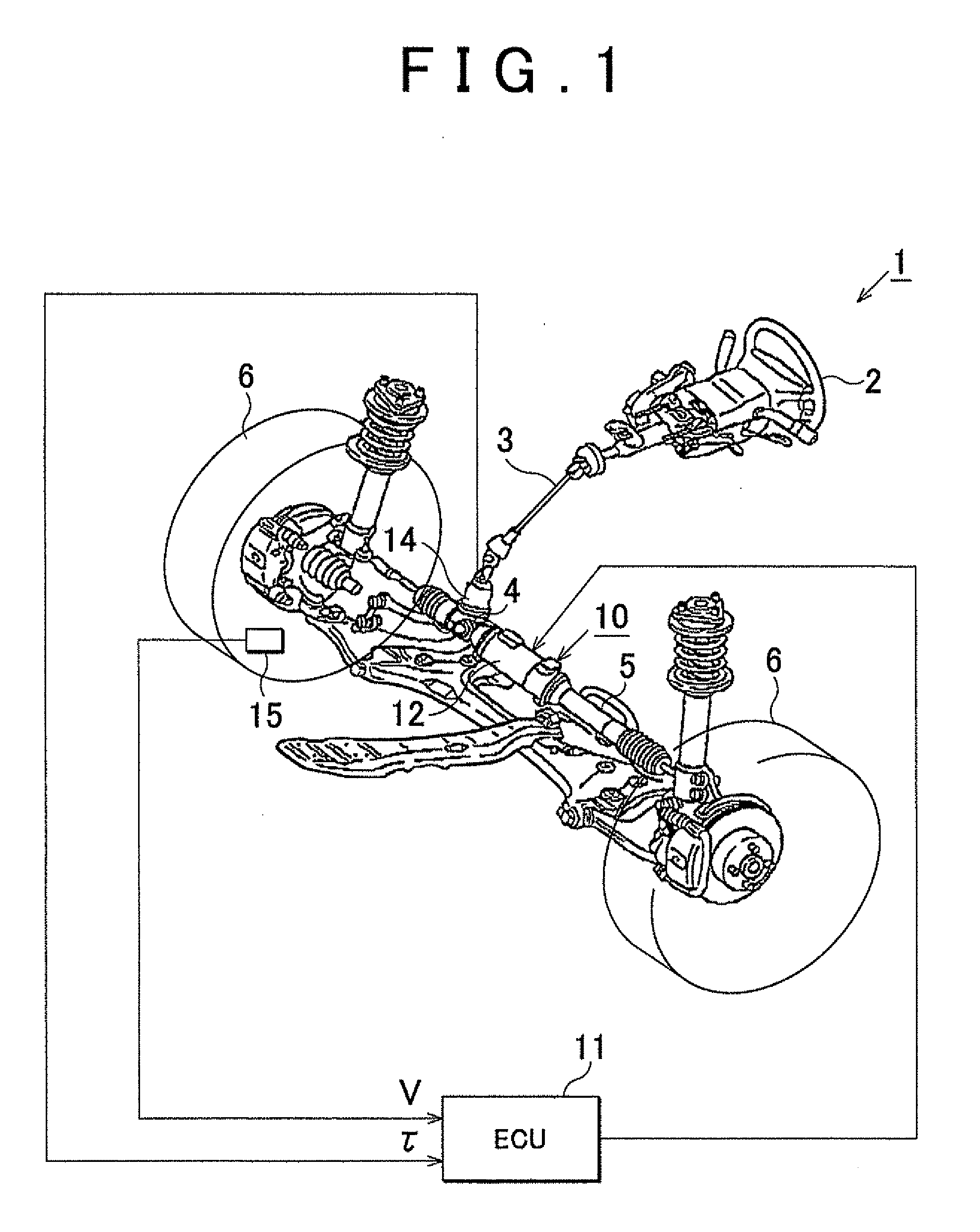
[0028]FIG. 1 is a view schematically showing the configuration of an electric power steering system (EPS) 1 according to the first embodiment. A steering shaft 3, to which a steering wheel 2 is fixed, is connected to a rack shaft 5 via a rack-and-pinion mechanism 4. The rotation of the steering shaft 3, caused in response to a steering operation, is converted into a linear reciprocation of the rack shaft 5 by the rack-and-pinion mechanism 4. The steering angle of steered wheels 6 is changed by the linear reciprocation of the rack shaft 5. As a result, the direction in which a vehicle travels is changed.

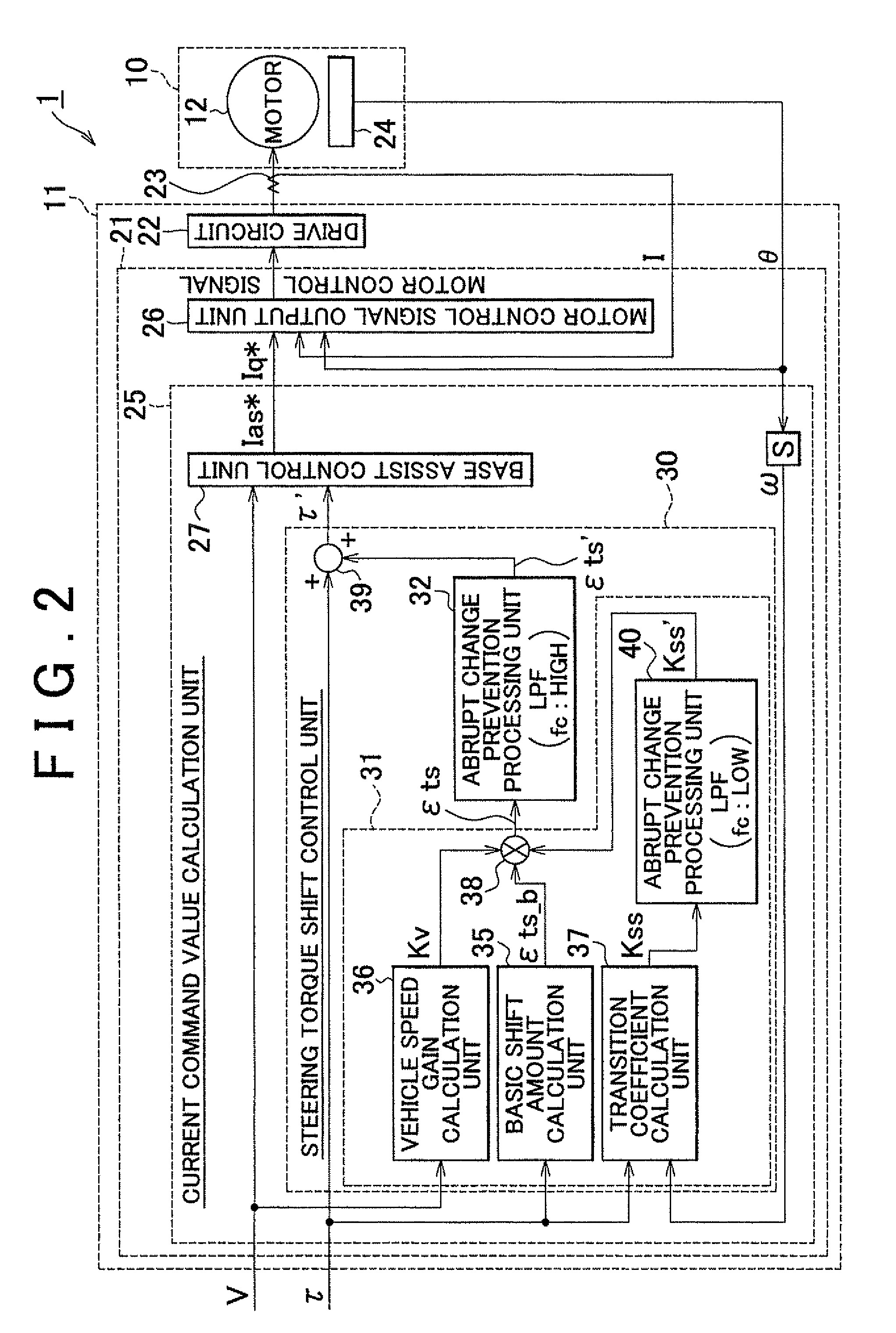
[0029]The EPS 1 includes an EPS actuator 10 and an ECU 11. The EPS actuator 10 serves as a steering force assisting device that supplies a steering system with assist force for assisting a steering operation. The ECU 11 serves as a control unit that controls an operation of the EPS actuator 10...

second embodiment

[0061]The abrupt change prevention processing unit 41 receives the transition coefficient Kss that is calculated by the transition coefficient calculation unit 37. The abrupt change prevention processing unit 41 changes the cutoff frequency (fc) of the low-pass filter based on the steering state indicated by the transition coefficient Kss.

[0062]When the steering state indicated by the transition coefficient Kss is the steering angle decreasing state or the steering angle maintained state, the cutoff frequency is set to a low value. On the other hand, when the steering state indicated by the transition coefficient is the steering angle increasing state, the cutoff frequency is set to a high value.

[0063]The cutoff frequency of the low-pass filter that forms the abrupt change prevention processing unit 41 is set to a value lower than the cutoff frequency of the low-pass filter that forms the abrupt change prevention processing unit 32 that executes the filter process on the steering t...


PUM


Abstract

A steering torque shift control amount calculation unit (31) calculates the steering torque shift control amount (εts) by multiplying the basic shift amount (εts_b) used as the basic compensation component by the transition coefficient (Kss). Then, the steering torque shift control amount (εts) is subjected to the low-pass filter process in an abrupt change prevention processing unit (32). An abrupt change prevention processing unit (40) is provided in the steering torque shift control amount calculation unit (31). The transition coefficient (Kss) is subjected to the low-pass filter process in the abrupt change prevention processing unit (40). The cutoff frequency of the low-pass filter that forms the abrupt change prevention processing unit (40) is set to a value lower than the cutoff frequency of the low-pass filter that forms the abrupt change prevention processing unit (32) that executes the low-pass filter process on the torque shift control amount (εts).

Description

INCORPORATION BY REFERENCE[0001]The disclosure of Japanese Patent Application No. 2009-146666 filed on Jun. 19, 2009 including the specification, drawings and abstract is incorporated herein by reference in its entirety.BACKGROUND OF THE INVENTION[0002]1. Field of the Invention[0003]The invention relates to an electric power steering system.[0004]2. Description of the Related Art[0005]In an electric power steering system (EPS) that uses a motor as a drive source, various compensation controls are executed in order to provide a good steering feel.[0006]The states of a steering operation performed by a driver (steering states) are broadly grouped into the steering angle increasing state, the steering angle maintained state, and the steering angle decreasing state. In the steering angle increasing state, the steering angle is increased. In the steering angle maintained state, the steering angle is maintained. In the steering angle deceasing state, the steering angle is decreased. The s...

Claims


Application Information

Patent Timeline
IPC IPC(8): G06F19/00B62D5/04B62D6/00B62D101/00B62D109/00B62D113/00B62D119/00
CPCB62D5/0463B62D6/00B62D5/0466
Inventor NISHIMURA, AKIHIKOTAMAIZUMI, TERUTAKAKITA, MASAYUKIAONO, SHINYAHASEGAWA, JUNNAMBU, AKIRA
Owner JTEKT CORP
Why Eureka
Try Eureka