Fuel gas purification apparatus, power generation system, and fuel synthesis system
a technology of fuel gas purification and power generation system, which is applied in the direction of combustible gas purification/modification, combustible gas production, machines/engines, etc., can solve the problems of increased cost and difficulty in enhancing the operability of equipment, and achieve the effect of simple configuration
- Summary
- Abstract
- Description
- Claims
- Application Information
AI Technical Summary
Benefits of technology
Problems solved by technology
Method used
Image
Examples
embodiment 1
[0070]The best mode for carrying out the present invention will be described below. The descriptions of the present embodiment are illustrative, and the present invention is not limited to the following descriptions.
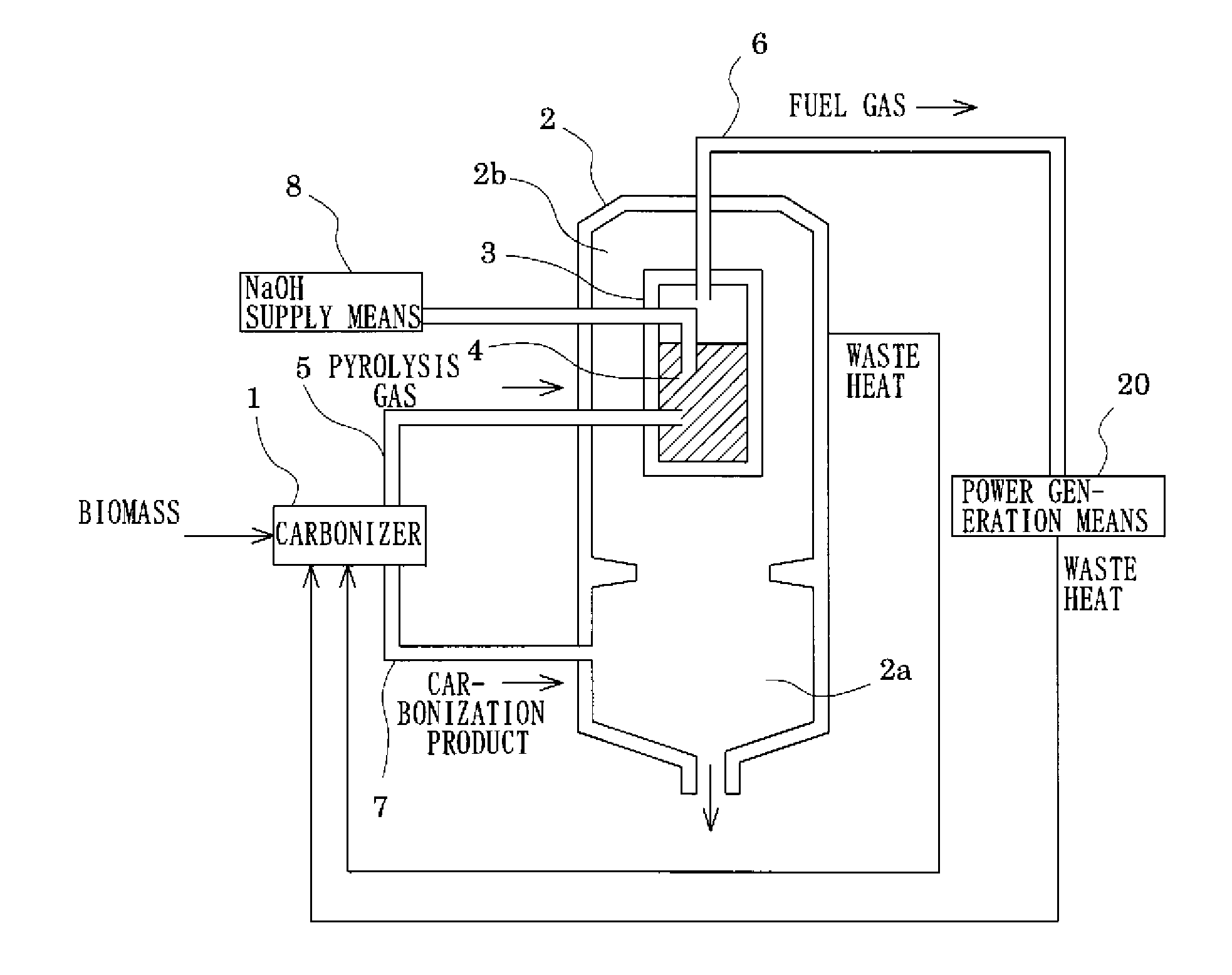
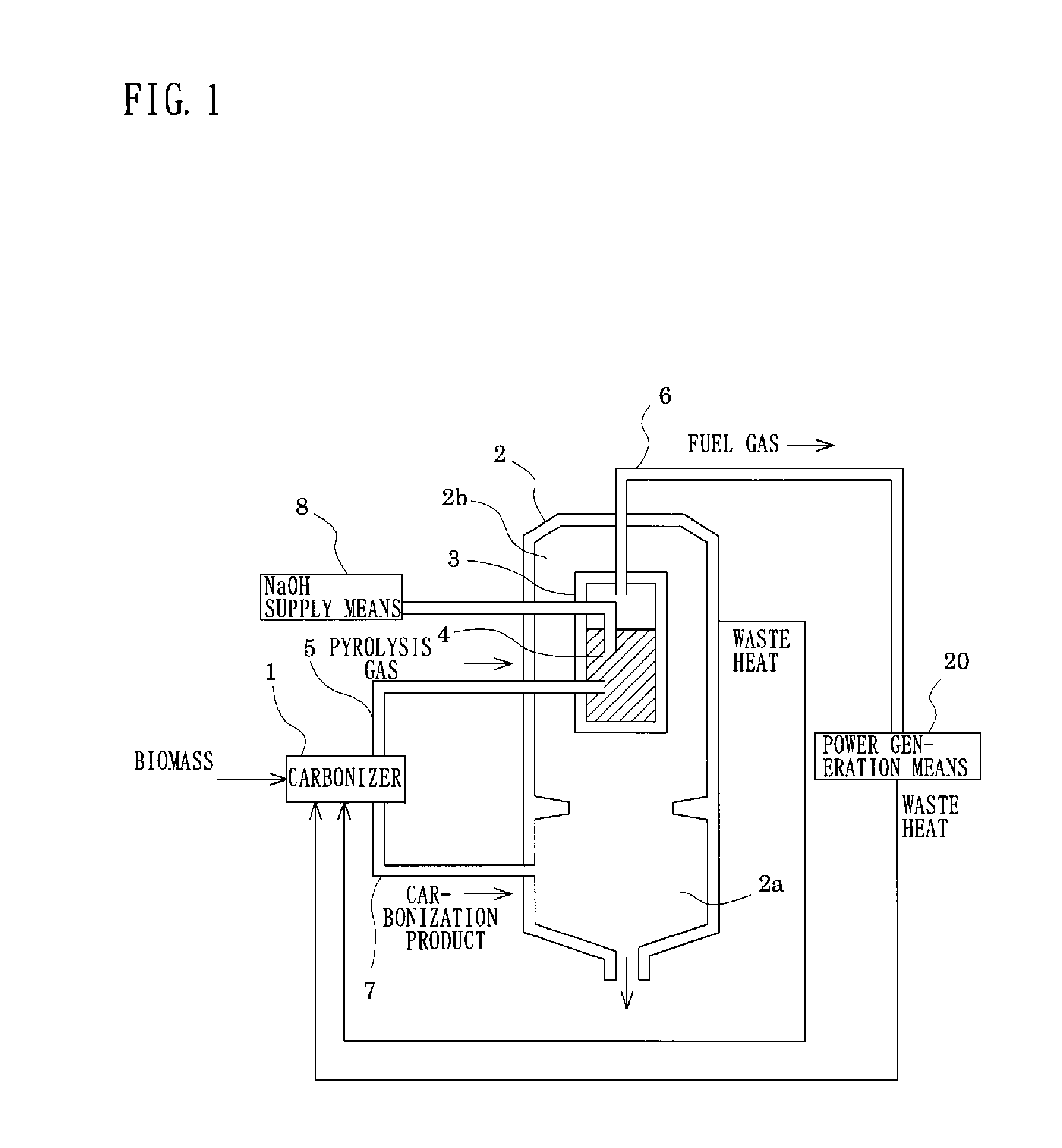
[0071]FIG. 1 is a schematic configurational drawing of a power generation system equipped with a fuel gas purification apparatus according to Embodiment 1.
[0072]As shown there, the fuel gas purification apparatus according to Embodiment 1 comprises a carbonizer 1 for pyrolyzing biomass, a furnace 2 for burning a carbonization product, a closed vessel 3 disposed within the furnace 2, an introduction pipe 5 for introducing a pyrolysis gas from the carbonizer 1 into the closed vessel 3, a carbonization product introduction pipe 7 for introducing the carbonization product from the carbonizer 1 into the furnace 2, a fuel gas supply pipe 6 for supplying a power generation means 20 with a fuel gas purified by the closed vessel 3, and a sodium hydroxide supply means 8 (in the dr...
embodiment 2
[0096]Embodiment 1 has explained the power generation system configured to supply the power generation means 20 with the fuel gas produced by the fuel gas purification apparatus. The present embodiment will explain a fuel synthesis system for synthesizing a liquid fuel from a fuel gas as a starting material.
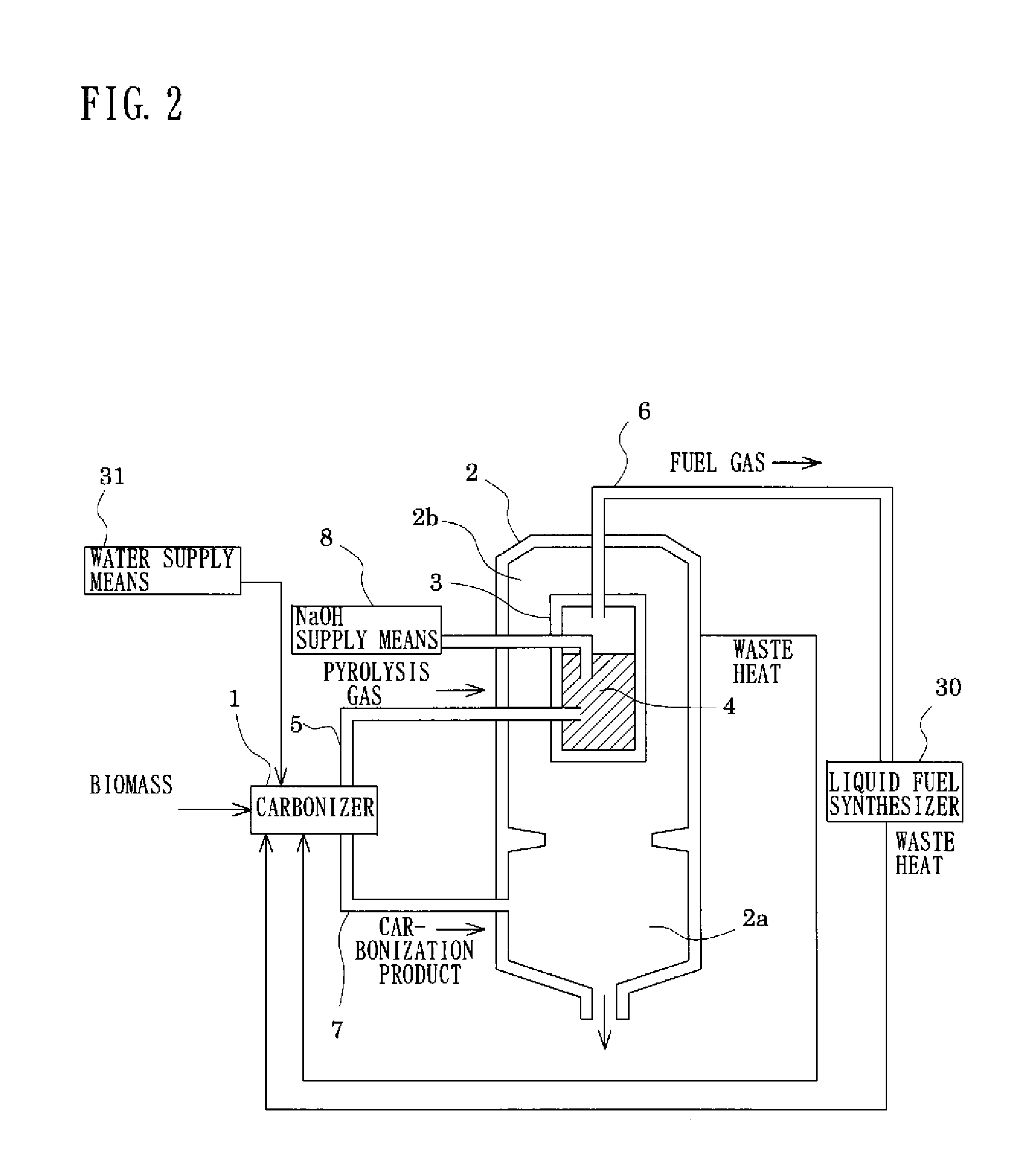
[0097]FIG. 2 is a schematic configurational drawing of a fuel synthesis system equipped with a fuel gas purification apparatus according to Embodiment 2. The same members as those in Embodiment 1 will be assigned the same numerals as in Embodiment 1, and duplicate explanations will be omitted.
[0098]The difference of the present embodiment from Embodiment 1 lies in providing a liquid fuel synthesizer 30 for synthesizing a liquid fuel using as a material a fuel gas supplied from a fuel gas supply pipe 6, and a water supply means 31 for supplying water to a carbonizer 1.
[0099]The liquid fuel synthesizer 30 is a device for synthesizing a hydrocarbon liquid fuel, such as methanol, dim...
embodiment 3
[0104]Embodiment 1 and Embodiment 2 are configured such that the carbonizer 1 is provided apart from the furnace 2, and the waste heat of the furnace 2 is imparted indirectly to the carbonizer 1 via a heat exchanger or the like. However, this configuration is not limitative.
[0105]FIG. 3 is a schematic perspective view of a carbonizer and a furnace according to Embodiment 3. FIG. 4 is a schematic configurational drawing of a power generation system equipped with a fuel gas purification apparatus according to Embodiment 3. The same members as those in Embodiment 1 are assigned the same numerals as in Embodiment 1, and duplicate explanations are omitted.
[0106]As shown in FIGS. 3 and 4, a carbonizer 1A is formed in a cylindrical shape, and is mounted on a furnace 2 such that the inner surface of the carbonizer 1A is in contact with the outer surface of the furnace 2.
[0107]Concretely, the carbonizer 1A is composed of an upper fixing portion 41, a lower fixing portion 42, and a body porti...
PUM
 Abstract
Description
Claims
Application Information
 - R&D
- Intellectual Property
- Life Sciences
- Materials
- Tech Scout
- Unparalleled Data Quality
- Higher Quality Content
- 60% Fewer Hallucinations
Browse by: Latest US Patents, China's latest patents, Technical Efficacy Thesaurus, Application Domain, Technology Topic, Popular Technical Reports.
© 2025 PatSnap. All rights reserved.Legal|Privacy policy|Modern Slavery Act Transparency Statement|Sitemap|About US| Contact US: help@patsnap.com


