
Refrigeration cycle apparatus

Inactive Publication Date: 2010-12-30
PANASONIC CORP
View PDF8 Cites 6 Cited by
  • Summary
  • Abstract
  • Description
  • Claims
  • Application Information

AI Technical Summary

Benefits of technology

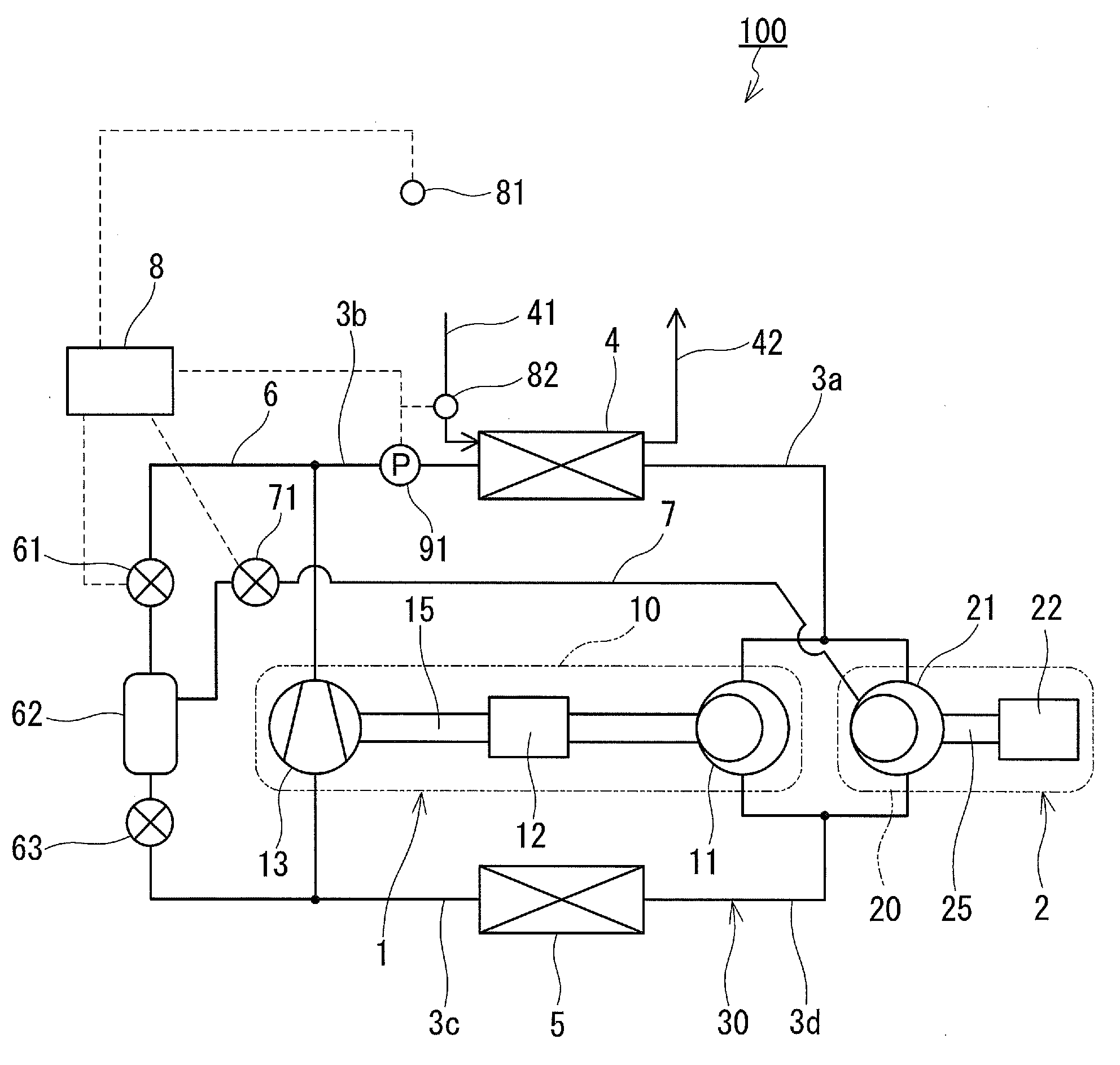
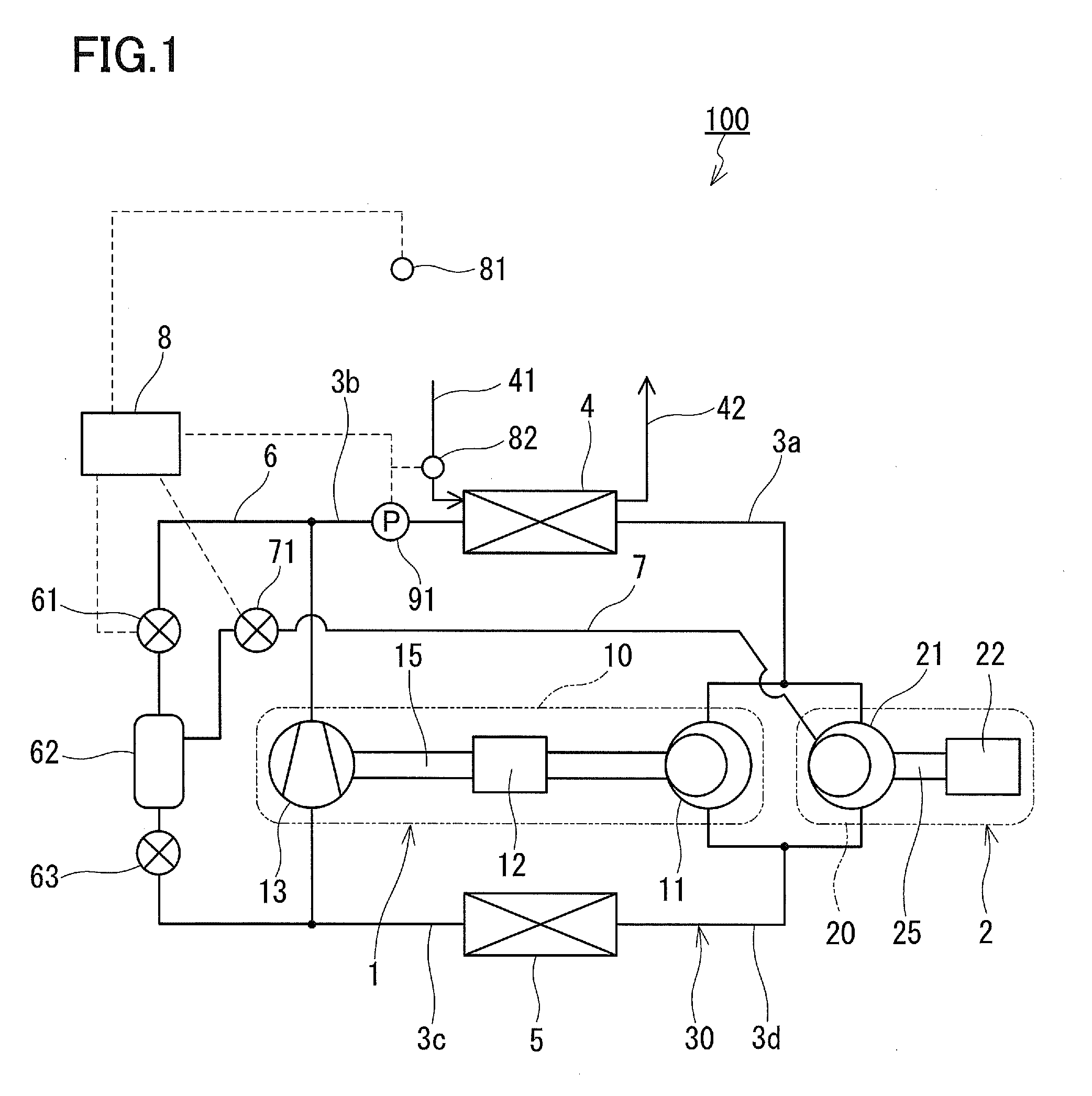
[0010]However, since the expander-compressor unit 100 has a configuration in which the expansion mechanism 103 is accommodated in a closed casing, the expander-compressor unit 100 has a lower temperature than that of the sub compressor 110. Moreover, since the closed casing of the expander-compressor unit 100 has a larger volumetric capacity than that of a closed casing of the sub compressor 110, the expander-compressor unit 100 radiates a larger amount of heat into the air. Accordingly, the temperature of the expander-compressor unit 100 becomes further lower than that of the sub compressor 110. Thus, when, for example, the rotation speed of the first motor 102 of the expander-compressor unit 100 is equal to that of the second motor 112 of the sub compressor 110, the refrigerant sent out from the expander-compressor unit 100 into the first pipe 141 has a lower temperature than that of the refrigerant sent out from the sub compressor 110 into the first pipe 141. In such a situation, when the refrigerant after the heat radiation is injected into the first compression mechanism 101 of the expander-compressor unit 100, the temperature of the refrigerant sent out from the expander-compressor unit 100 into the first pipe 141 is lowered further. As a result, the difference between the temperature of the refrigerant sent out from the compressor 100 to the first pipe 141 and the temperature of the refrigerant sent out from the compressor 110 to the first pipe 141 is increased. This means that the refrigerants having largely different temperatures are merged with each other, deteriorating the stability of the refrigeration cycle.
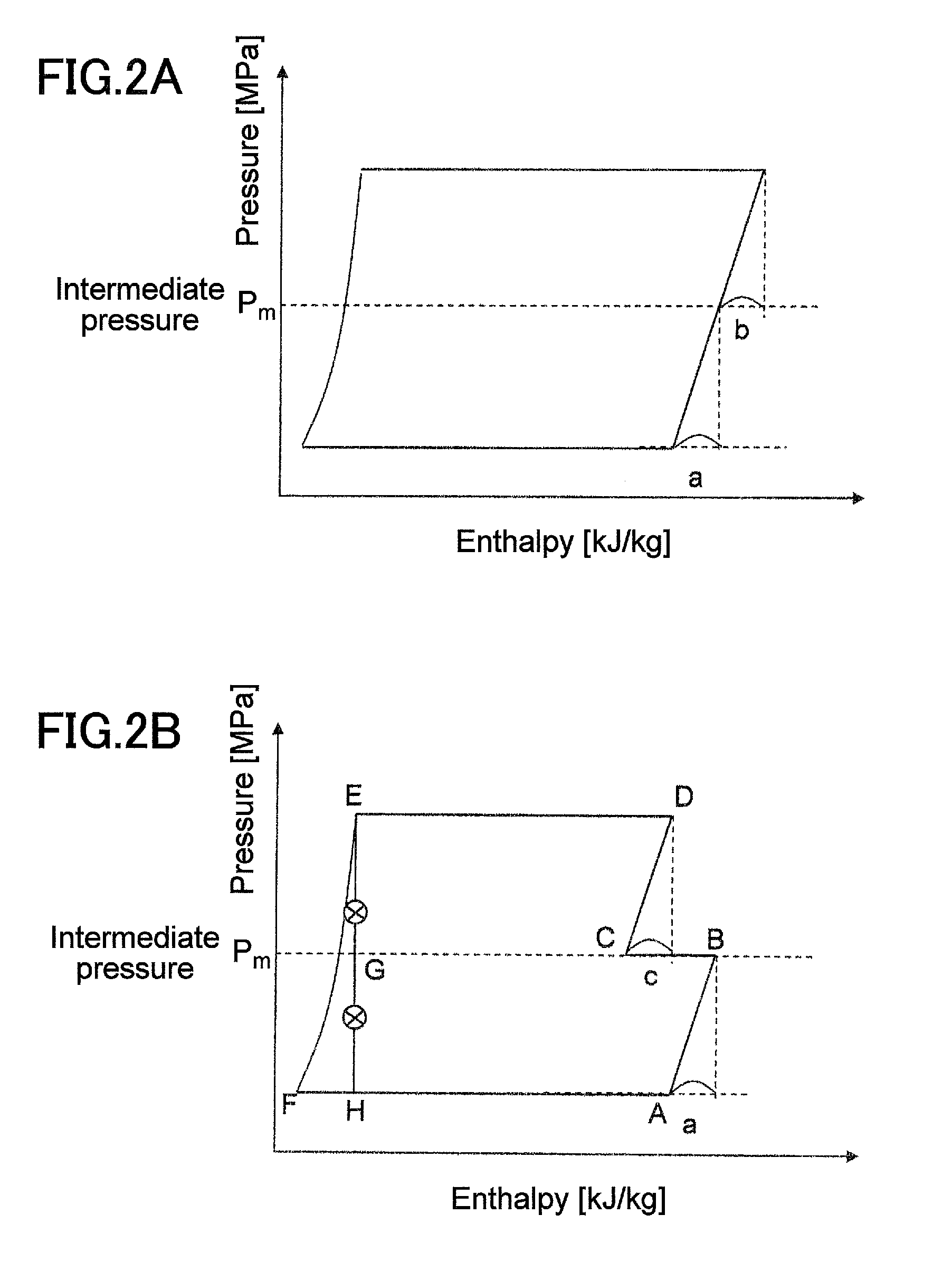
[0012]This configuration makes it possible to increase the circulation amount of the refrigerant passing through the radiator by the supply of the gas refrigerant to the second compression mechanism through the injection passage, that is, by so-called injection. This allows the heat radiating capacity to be increased temporarily while keeping the COP high. Moreover, the injection into the second compression mechanism can reduce the difference between the temperature of the refrigerant sent out from the expander-compressor unit into the first pipe and the temperature of the refrigerant sent out from the sub compressor into the first pipe. Thereby, it is possible to increase the heat radiating capacity without spoiling the stability of the refrigeration cycle but rather while keeping it in a satisfactory state.

Problems solved by technology

This means that the refrigerants having largely different temperatures are merged with each other, deteriorating the stability of the refrigeration cycle.

Method used


Image

  • Refrigeration cycle apparatus
  • Refrigeration cycle apparatus
  • Refrigeration cycle apparatus

Examples


modified example

[0048]Although the fixed throttle is used as the second flow control valve 63 in the above-mentioned embodiment, it also is possible to use an expansion valve as the second flow control valve 63. In this case, a second pressure sensor (a second pressure detecting means) 92 for detecting the pressure in the gas-liquid separator 62 may be provided as in a refrigeration cycle apparatus 100A according to a modified example shown in FIG. 4, and the opening of the second flow control valve 63 may be adjusted by the controller 8 so that the intermediate pressure Pm detected by the pressure sensor 92 becomes equal to or higher than the specified pressure Pb. In the example shown in FIG. 4, the pressure sensor 92 is provided to the bypass passage 6, between the first flow control valve 61 and the gas-liquid separator 62.

[0049]Or, instead of the pressure sensor 92, a refrigerant temperature sensor 84 for detecting the temperature of the refrigerant in the gas-liquid separator 62 may be provid...


PUM


Abstract

A refrigeration cycle apparatus (100) includes an expander-compressor unit (1) including a first compression mechanism (11) and an expansion mechanism (13), and a sub compressor (2) including a second compression mechanism (21). The first compression mechanism (11) is connected in parallel with the second compression mechanism (21) in a refrigerant circuit (30). The refrigeration cycle apparatus (100) further includes a bypass passage (6) bypassing the expansion mechanism (13). A first flow control valve (61), a gas-liquid separator (62) and a second flow control valve (63) are provided sequentially to the bypass passage (6) from an upstream side. An injection passage (7) guides a gas refrigerant separated from a liquid refrigerant in the gas-liquid separator (62) to the second compression mechanism (21).

Description

TECHNICAL FIELD[0001]The present invention relates to a refrigeration cycle apparatus used for water heaters, air conditioners, etc., having an expansion mechanism and compression mechanisms.BACKGROUND ART[0002]In recent years, for the purpose of further enhancing the efficiencies of refrigeration cycle apparatuses, there have been proposed power recovery type refrigeration cycle apparatuses using an expansion mechanism instead of an expansion valve, in which the expansion mechanism recovers the pressure energy as power during a process in which a refrigerant is expanded, and thus the electric power required for driving the compression mechanism is reduced by the amount of the power recovered. Such refrigeration cycle apparatuses use an expander-compressor unit, in which a motor, a compression mechanism, and an expansion mechanism are coupled by a shaft.[0003]Since the compression mechanism is coupled to the expansion mechanism by the shaft in the expander-compressor unit, the refri...

Claims


Application Information

Patent Timeline
IPC IPC(8): F25B41/00F25B1/10
CPCF25B1/10F25B2700/21161F25B9/06F25B2309/061F25B2339/047F25B2341/0662F25B2400/0411F25B2400/075F25B2400/13F25B2600/17F25B2600/2509F25B2700/2106F25B2700/2109F25B2700/21152F25B9/008F25B41/39
Inventor HONMA, MASAYAYAKUMARU, YUICHITANIGUCHI, KATSUJIMATSUMOTO, SUBARU
Owner PANASONIC CORP
Learn More