Keyboard apparatus

a technology of keyboard and key, applied in the field of keyboard apparatus, can solve the problems of difficult to reproduce or reproduce the key touch feeling of an acoustic piano with high accuracy, complicated action mechanism, and inability to faithfully reproduce the units of electronic keyboard instruments, and achieve the effect of smooth driving force transmission and simple construction

Inactive Publication Date: 2010-12-30
YAMAHA CORP
View PDF27 Cites 5 Cited by
  • Summary
  • Abstract
  • Description
  • Claims
  • Application Information

AI Technical Summary

Benefits of technology

[0010]In view of the foregoing, it is an object of the present invention to provide an improved keyboard apparatus which is simple in construction and yet can achieve creation of a key touch feeling approximate to that of a natural keyboard instrument by achieving smooth driving force transmission between component parts, such as a key and a mass member.

Problems solved by technology

However, in the electronic keyboard instruments, which generate an electronic tone in response to depression of a key, there is provided no mechanism that actually strikes strings to generate an electronic tone and hence no complicated action mechanism as in the natural keyboard instruments.
Consequently, the keyboard units of the electronic keyboard instruments cannot faithfully reproduce a key touch feeling provided through the action mechanism of the natural keyboard instruments, and thus, strictly speaking, the key touch feeling provided by the electronic keyboard instruments is different from that provided by the natural keyboard instruments.
With the keyboard unit disclosed in Patent Literature 1, where behavior of the key is controlled by the solenoid alone, it is difficult to replicate or reproduce a key touch feeling of an acoustic piano with high accuracy.
Thus, these separately-provided mass member and actuator have different operating systems, so that there are limitations to appropriately controlling, through driving of the actuator, a load applied from the mass member to the key.
However, in the case where the behavior of the key is controlled by the springs, even if auxiliary force sense control of the key is performed through driving of the actuator, the keyboard apparatus disclosed in Patent Literature 3 cannot faithfully reproduce an inertial mass feeling characteristic of behavior of a key of a natural keyboard instrument, such as an acoustic piano.
Particularly, whereas, in an acoustic piano, movement of a key has to be started at the start of depression of the key against a static load of a string-striking hammer, it is difficult for the keyboard apparatus disclosed in Patent Literature 3 to appropriately reproduce an operational feeling at the start of depression of a key on an acoustic piano.
Further, even if the springs provided in the keyboard apparatus disclosed in Patent Literature 3 are replaced with a mass member that generates an inertial force in interlocked relation to movement of the key, a possibility of properly controlling a load applied from the mass member to the key through driving of the actuator would be limited because the mass member is provided separately from the actuator and because the mass member and the actuator differ in operating system.

Method used


Image

  • Keyboard apparatus
  • Keyboard apparatus
  • Keyboard apparatus

Examples


first embodiment

[0047]First, first to fourth embodiments will be described, with reference to FIGS. 2 to 10, as embodiments employing novel arrangements common to first and second aspects of the present invention.

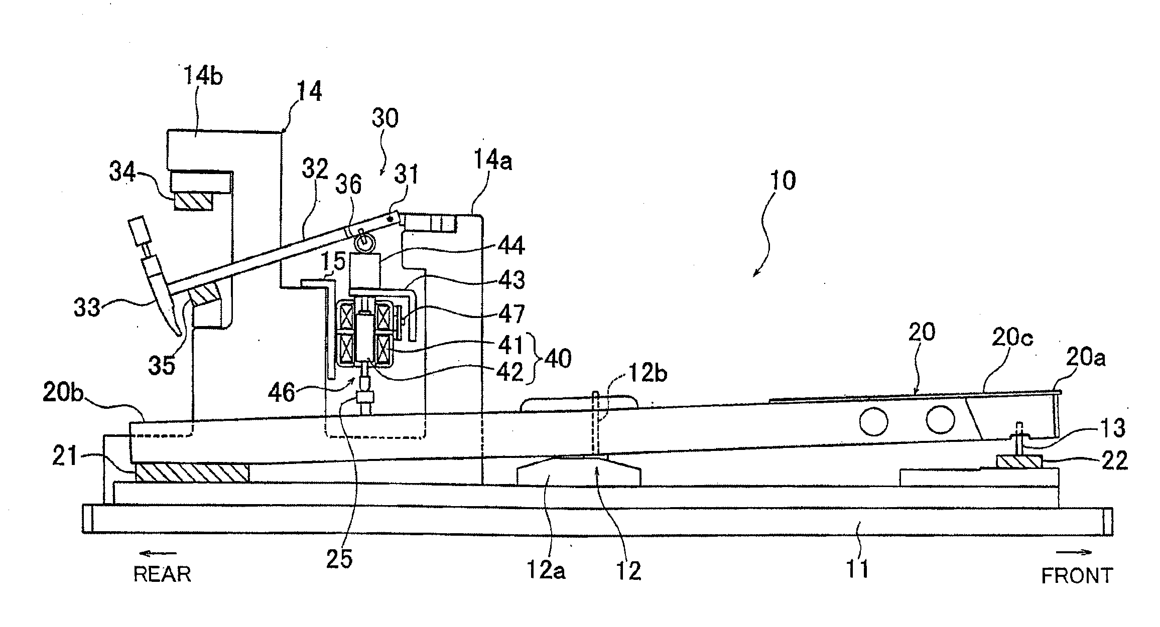
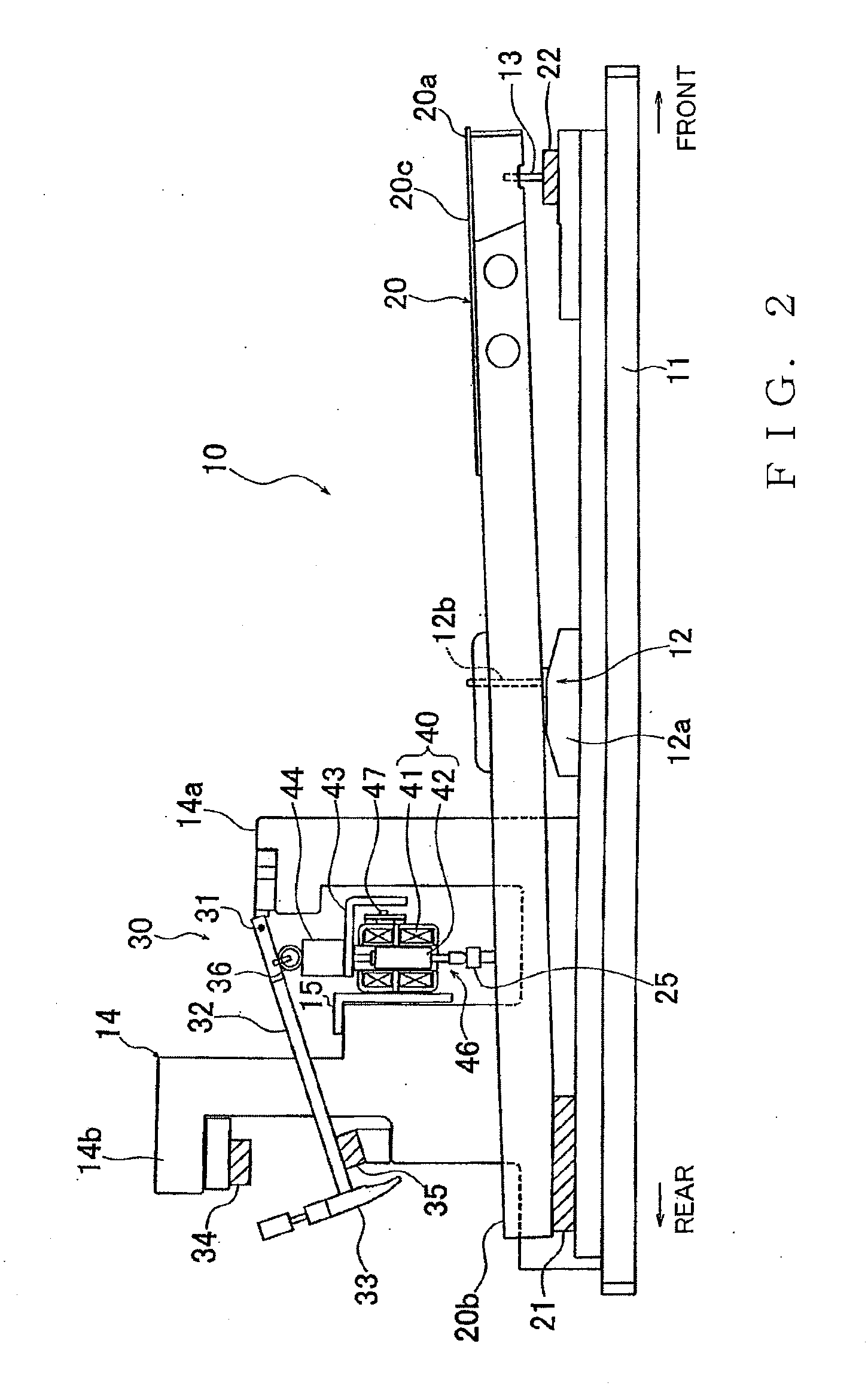
[0048]FIG. 2 is a schematic side view of the first embodiment of the keyboard apparatus 10, which particularly shows one of the keys 20 and other component parts around the key 20. FIG. 3 is a fragmentary enlarged side view showing detailed constructions of a later-described electromagnetic actuator (driving force imparting section) 40 and other component parts around the actuator 40. Further, FIG. 4 is a view explanatory of behavior of the keyboard apparatus 10, of which FIG. 4A shows a state where the key 20 is in a non-depressed position while FIG. 4B shows a state in which the key 20 is in a depressed position. The keyboard apparatus 10 includes a frame 11 of a flat plate shape that forms part of the electronic keyboard instrument 1, the keys 20 and mass members (i.e., pseudo hammers) ...

second embodiment

[0093]Next, a description will be given about a second embodiment of the keyboard apparatus of the present invention. Similar elements to those in the first embodiment are indicated by the same reference numerals as used for the first embodiment and will not be described here to avoid unnecessary duplication. Namely, elements not described in the following description are similar to those in the first embodiment; the same can be said for the third and succeeding embodiments.

[0094]FIG. 8 is a view showing a construction of the second embodiment of the keyboard apparatus 10-2, which includes a uni-directionally driven electromagnetic actuator 40-2 in place of the bi-directionally driven electromagnetic actuator 40 provided in the first embodiment of the keyboard apparatus 10. In other structural respects, the second embodiment of the keyboard apparatus 10-2 is similar to the first embodiment of the keyboard apparatus 10. More specifically, the uni-directionally driven electromagnetic ...

third embodiment

[0097]Next, a description will be given about a third embodiment of the keyboard apparatus of the present invention. FIG. 9 is a view showing a construction of the third embodiment of the keyboard apparatus 10-3. Whereas the electromagnetic actuator 40 in the first embodiment of the keyboard apparatus 10 is provided in such a manner that the respective axes of the projecting coil 41a, retracting coil 41b and plunger 42 are oriented in the vertical direction, the electromagnetic actuator 40-3 in the third embodiment of the keyboard apparatus 10-3 is provided in such a manner that the respective axes of the projecting coil 41a, retracting coil 41b and plunger 42 are slightly inclined with respect to the vertical direction. In other structural respects, the third embodiment of the keyboard apparatus 10-3 is similar to the first embodiment of the keyboard apparatus 10.

[0098]Specifically, the rear wall 14b of the support section 14 supporting the electromagnetic actuator 40-3 is inclined...


PUM


Abstract

In a keyboard apparatus including a key supported for pivoting movement about a pivot point, a mass member that imparts a reaction force to performance operation of the key in interlocked relation to the key, and an electromagnetic actuator provided between the key and the mass member for imparting a driving force to the key and mass member, a transmission member is provided in detachable abutment with the key and mass member. The transmission member can be disengaged from the key or the mass member depending on operating conditions of the key and the mass member. Thus, it is possible to not only prevent unnecessary binding forces from acting in areas where the transmission member and the key and the mass member abut against each other, but also achieve smooth movement of the key and the mass member and prevent increase of inertial mass of the transmission member. The smooth movement of the key and mass member can achieve force sense control with good responsiveness. Further, the key is pivotable in a key depressing direction as a reaction force imparted from the mass member is reduced by impartment, to the key, of a driving force by the actuator. Thus, the apparatus can perform both force sense control on depression operation of the key and an automatic performance involving automatic operation of the key, through cooperation between a reaction force imparted from the mass member to the key and the driving force imparted from the actuator to the key.

Description

BACKGROUND[0001]The present invention relates generally to keyboard apparatus provided in electronic keyboard instruments etc., and more particularly to a keyboard apparatus provided with force sense control and operation control functions for controlling an operational feeling and behavior of keys.[0002]Keyboard units of natural keyboard instruments, such as acoustic pianos, which generate raw tones, are constructed to generate a tone by a hammer, pivoting in response to depression of a key, striking strings. In these keyboard units, an action mechanism, including a jack and a wippen, is provided between each key and a corresponding hammer. Such an action mechanism allows a characteristic reaction force to be applied from the key to a human player's finger. Thus, in the keyboard unit of a natural keyboard instrument, a key touch feeling characteristic of, or unique to, the keyboard instrument can be obtained.[0003]Keyboard units of electronic keyboard instruments which generate ele...

Claims


Application Information

Patent Timeline
Patent Type & Authority Applications(United States)
IPC IPC(8): G10H1/18
CPCG10H2220/311G10H1/346
Inventor YAGUCHI, NARIYASUKOMATSU, AKIHIKOHAYASHI, YOSHINORI
Owner YAMAHA CORP
Why Eureka
Try Eureka