Apparatus for etching substrate and method of fabricating thin-glass substrate
a technology of etching apparatus and substrate, which is applied in the manufacture of layered products, chemistry apparatus and processes, cable/conductor manufacturing, etc., can solve the problems of deteriorating etching uniformity, slow through-put, and inability to uniformly etch glass substrate at a high etching rate, so as to achieve high etching rate and effectively prevent the attachment of minute particles
- Summary
- Abstract
- Description
- Claims
- Application Information
AI Technical Summary
Benefits of technology
Problems solved by technology
Method used
Image
Examples
first exemplary embodiment
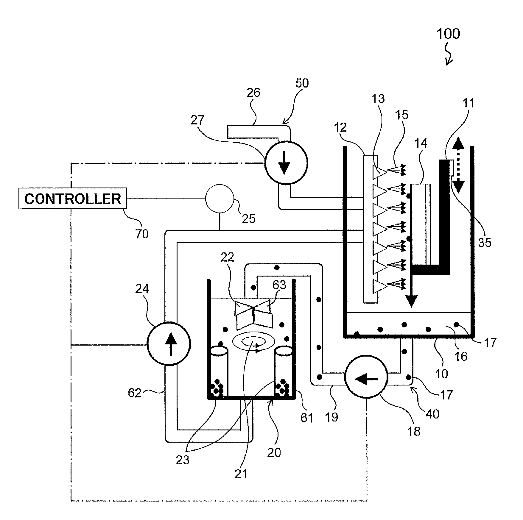
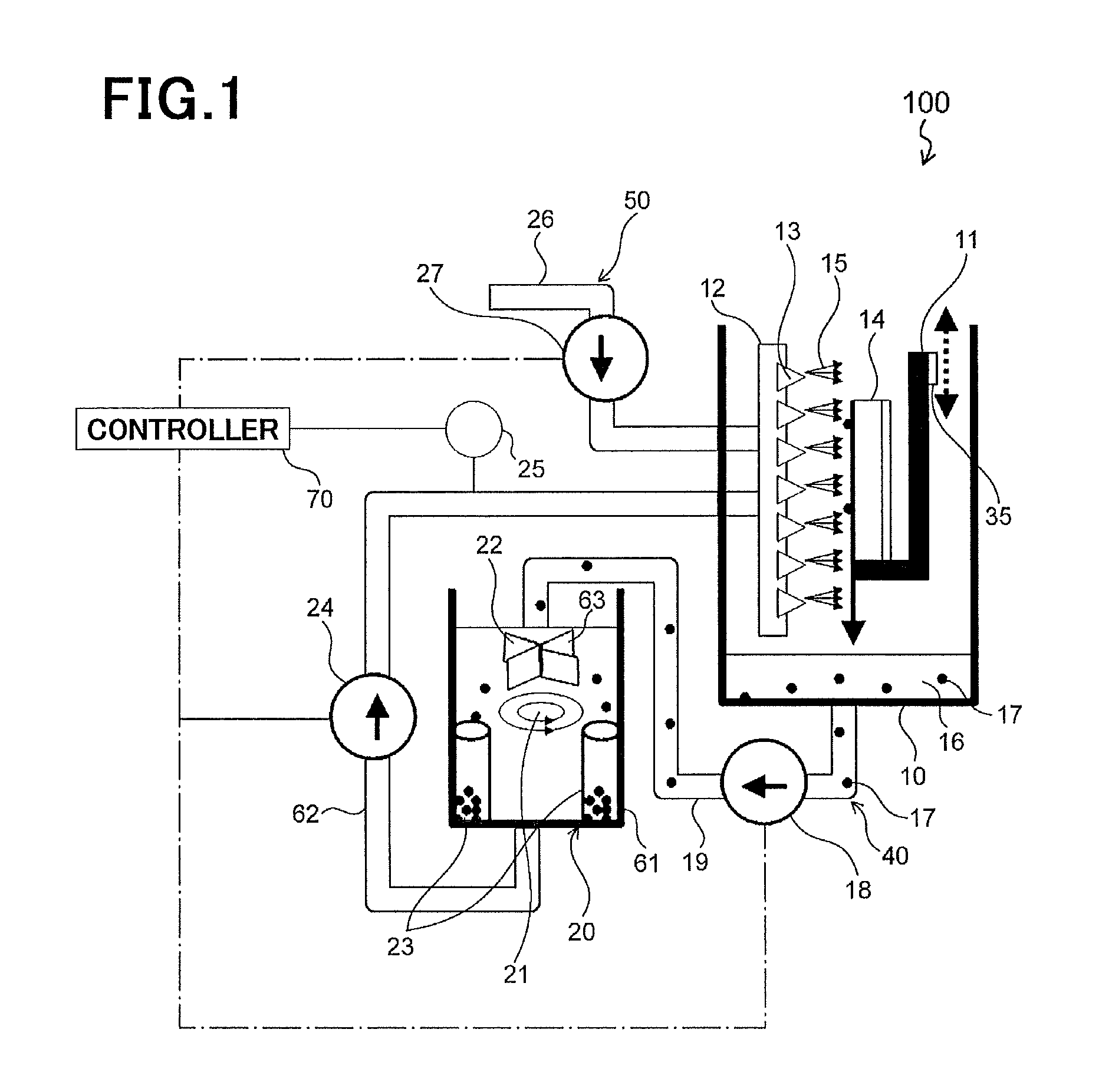
[0043]FIG. 1 illustrates an etching apparatus 100 for etching a substrate, in accordance with the first exemplary embodiment.
[0044]As illustrated in FIG. 1, the etching apparatus 100 is comprised of an etching bath 10 in which a substrate 14 is etched, a substrate holder 11 holding the substrate 14 in the etching bath 10, a nozzle system 12 which sprays acid solution 16 to the substrate 14 held by the substrate holder 11, a mover 35 which moves the substrate holder 11 relative to the substrate 14, a filter system 20 which removes impurities out of the acid solution before the acid solution is supplied again to the nozzle system 12 after the acid solution was sprayed onto the substrate 14, a circulation system 40 which supplies the acid solution contained in the etching bath 10 after having been sprayed onto the substrate 14, again to the nozzle system 12 through the filter system 20, and a water supply system 50 which supplies water to the nozzle system 12.
[0045]The etching apparatu...
second exemplary embodiment
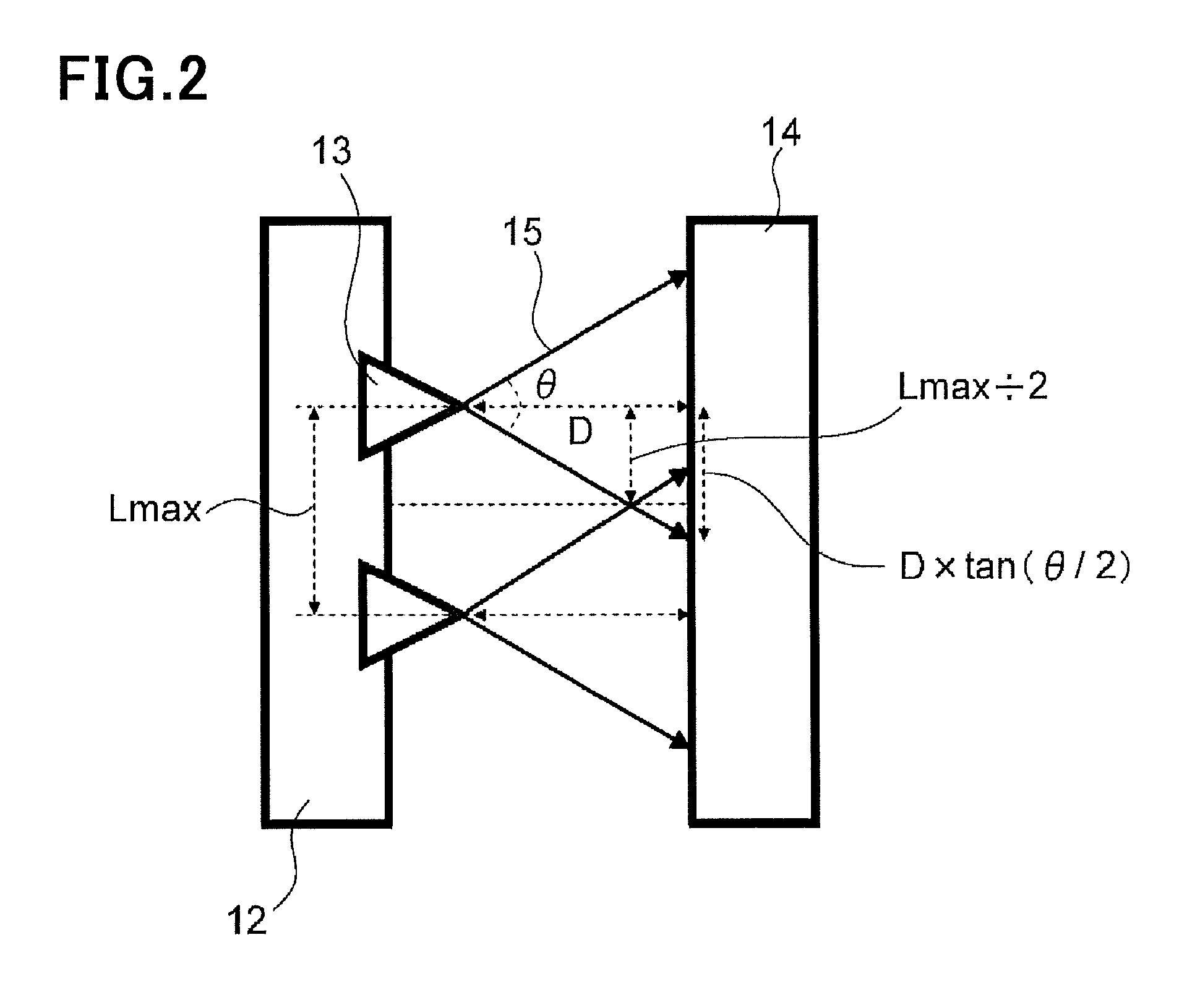
[0097]In an etching apparatus in accordance with the second exemplary embodiment, a relation among a distance D between a surface of the substrate 14 and the nozzle 13, a maximum space Lmax between the nozzles 13 disposed adjacent to each other in the nozzle system 12, and an angle θ by which the acid solution 16 or water sprayed out of the nozzle 13 expands is defined to thereby enhance uniformity in etching the substrate 14 in a plane thereof.
[0098]FIG. 2 is an enlarged view of a part of an etching apparatus in accordance with the second exemplary embodiment.
[0099]Specifically, FIG. 2 illustrates only the nozzle system 12 and the substrate 14 held by the substrate holder 11 (not illustrated in FIG. 2).
[0100]In an etching apparatus in accordance with the second exemplary embodiment, the distance D, the maximum space Lmax, and the angle θ are defined in accordance with the relation (A), as illustrated in FIG. 2.
Lmax / 2D×tan(θ / 2) (A)
[0101]By defining the distance D, the maximum space...
third exemplary embodiment
[0106]In an etching apparatus in accordance with the third exemplary embodiment, a relation between a maximum space Lmax between the nozzles 13 disposed adjacent to each other in the nozzle system 13, and a minimum length Mmin by which at least one of the nozzle system 12 and the substrate 14 is moved by the mover 35 is defined to thereby enhance uniformity in etching the substrate 14 in a plane thereof.
[0107]FIG. 3 is an enlarged view of a part of an etching apparatus in accordance with the third exemplary embodiment.
[0108]Specifically, FIG. 3 illustrates only the nozzle system 12 and the substrate 14 held by the substrate holder 11 (not illustrated in FIG. 3).
[0109]In an etching apparatus in accordance with the third exemplary embodiment, the maximum space Lmax and the minimum length Mmin are defined in accordance with the relation (B), as illustrated in FIG. 3.
Lmax / 2<Mmin (B)
[0110]By defining the maximum space Lmax and the minimum length Mmin in accordance with the relation (...
PUM
| Property | Measurement | Unit |
|---|---|---|
| contrast | aaaaa | aaaaa |
| contrast | aaaaa | aaaaa |
| size | aaaaa | aaaaa |
Abstract
Description
Claims
Application Information
 - R&D
- Intellectual Property
- Life Sciences
- Materials
- Tech Scout
- Unparalleled Data Quality
- Higher Quality Content
- 60% Fewer Hallucinations
Browse by: Latest US Patents, China's latest patents, Technical Efficacy Thesaurus, Application Domain, Technology Topic, Popular Technical Reports.
© 2025 PatSnap. All rights reserved.Legal|Privacy policy|Modern Slavery Act Transparency Statement|Sitemap|About US| Contact US: help@patsnap.com


