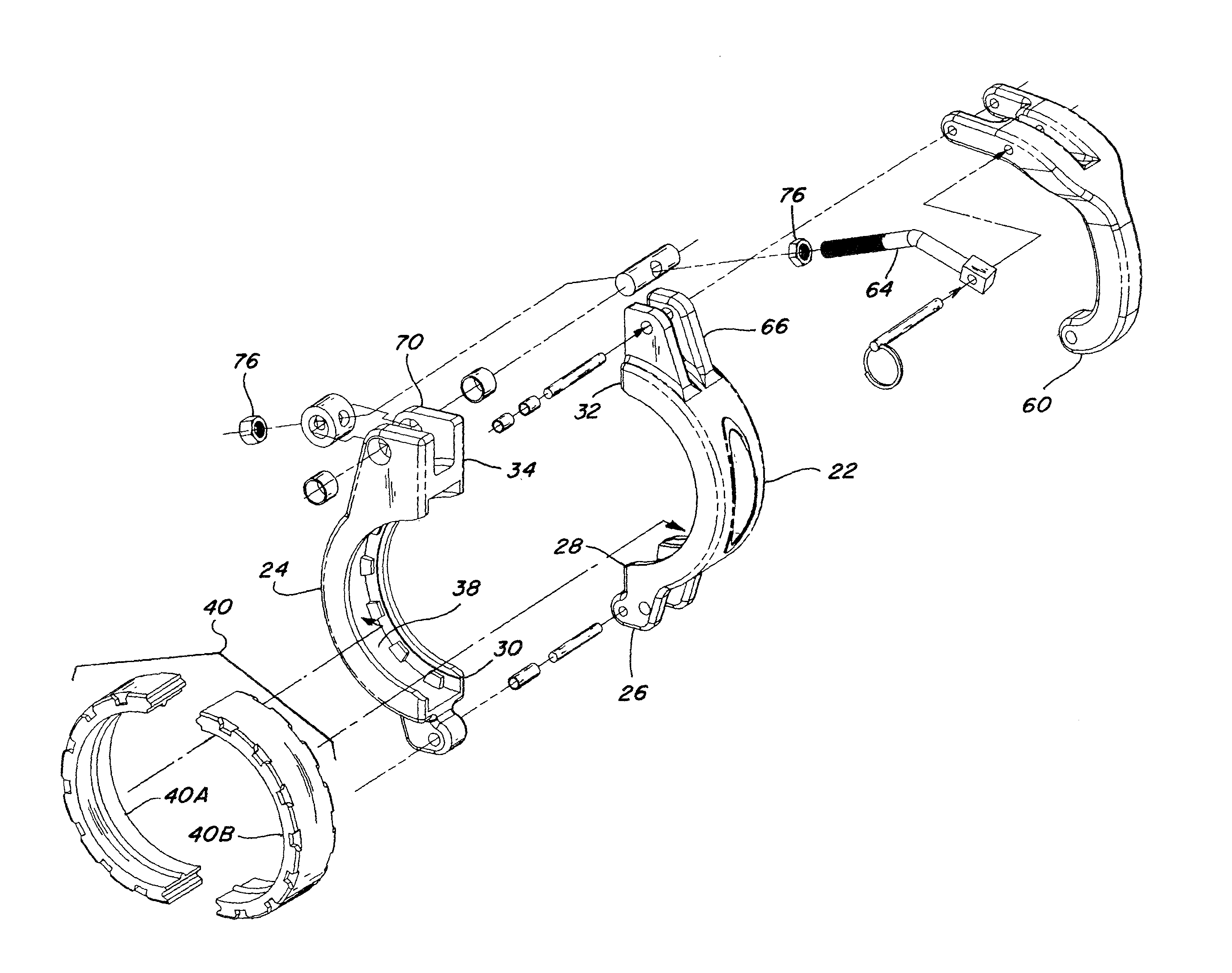
[0016]The gasket retaining elements on the semi-circular elements preferably comprise projections or raised tabs or features disposed in a circumferentially extending spaced apart array about the radial outer periphery of the cavities or channels, and the elements on the gasket comprise correspondingly located receptacles sized and shaped for receiving and engaging the retaining elements when the gasket is shaped to the circumference of the cavity or channel. In this regard, the gasket will typically comprise a flexible
elastomer or
rubber material with at least some resiliency, having a generally straight overall
free state shape, at least initially, but can also comprise a pre-curved shape. In either instance, the gasket will typically be required to be curved or bent, at least at first, typically manually, to a curvature having a
radius marginally smaller than the
radius of the cavity or channel of the semi-circular element in which it is to be received and used. As a result, the circumferential surfaces defining and bounding the receptacles along the radial outer periphery will be deformed, e.g., spread apart or expanded at least marginally, so as to more easily receive the respective retaining elements. Then, when the gasket is released so as to seat in the cavity or channel, it will resiliently conform to the curved shape thereof, and compress about and grip the respective retaining elements, for retention in the cavity or channel. This retention also advantageously holds the gasket segments evenly at least about an extended
intermediate region of the circumference thereof, to prevent the gasket from sliding or moving along the inner circumferences of the semi-circular elements as the semi-circular elements are closed or brought together about the ends of two pipes or a pipe and a fitting for coupling, to avoid bunching of the gasket which can interfere with or prevent closure of the coupler, and unevenly compress or load the gasket in the circumferential direction.
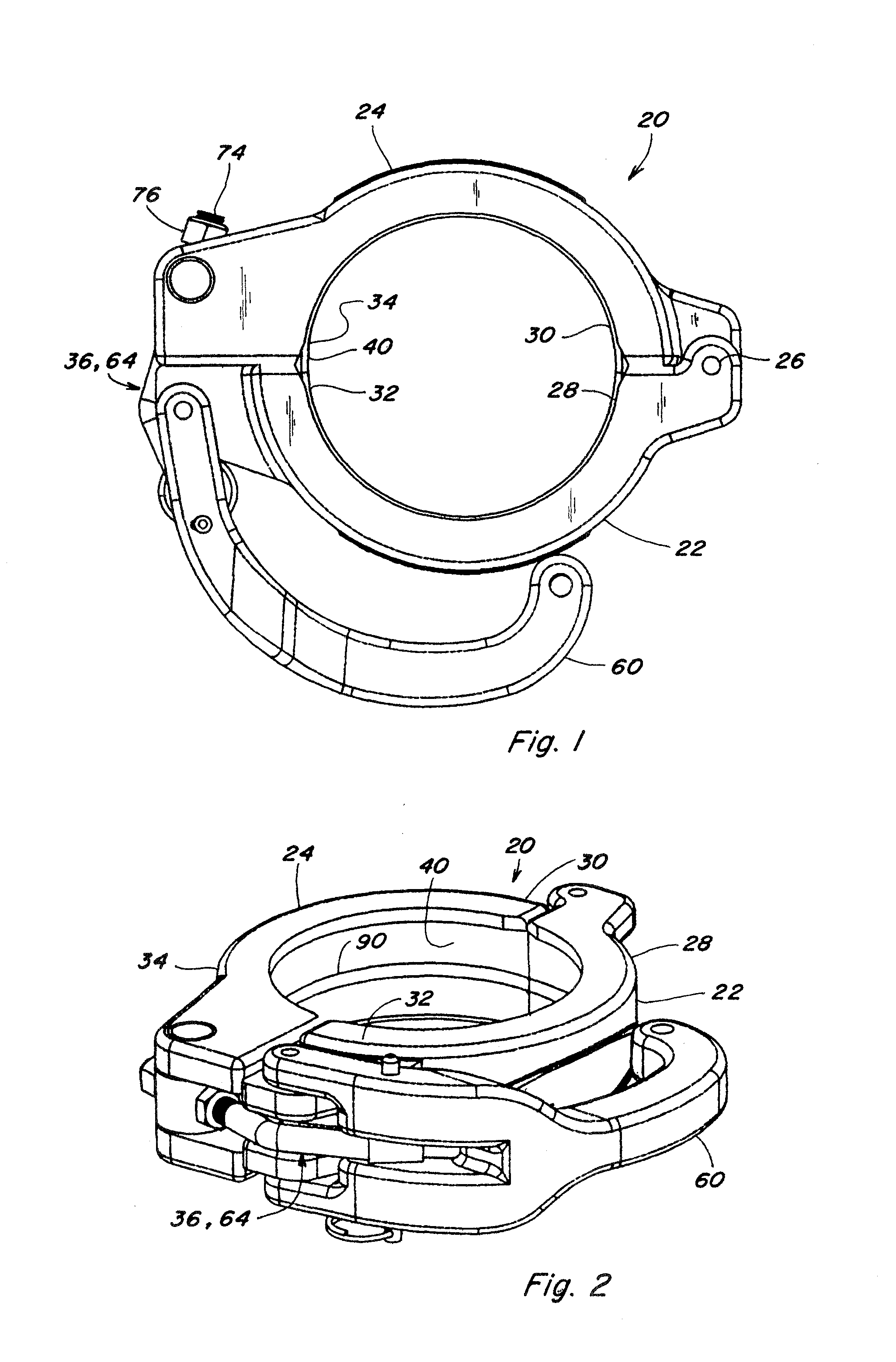
[0018]As a preferred feature of the clamping mechanism, it is configured to hold the second end portions of the semi-circular elements together when spread apart when the coupler is open. As a result, the coupler in the open configuration can be placed on a pipe end (without requiring sliding the gasket thereover as with an annular gasket), and held in place with just one hand without risk of the clamping mechanism coming apart, to allow the other hand to be used for handling the other pipe for positioning it for coupling. When the pipes are positioned for coupling, the clamping mechanism of the coupler can then be positioned about both pipe ends (again without sliding the gasket) and operated to clamp the coupler with just one hand, to couple the pipes together.
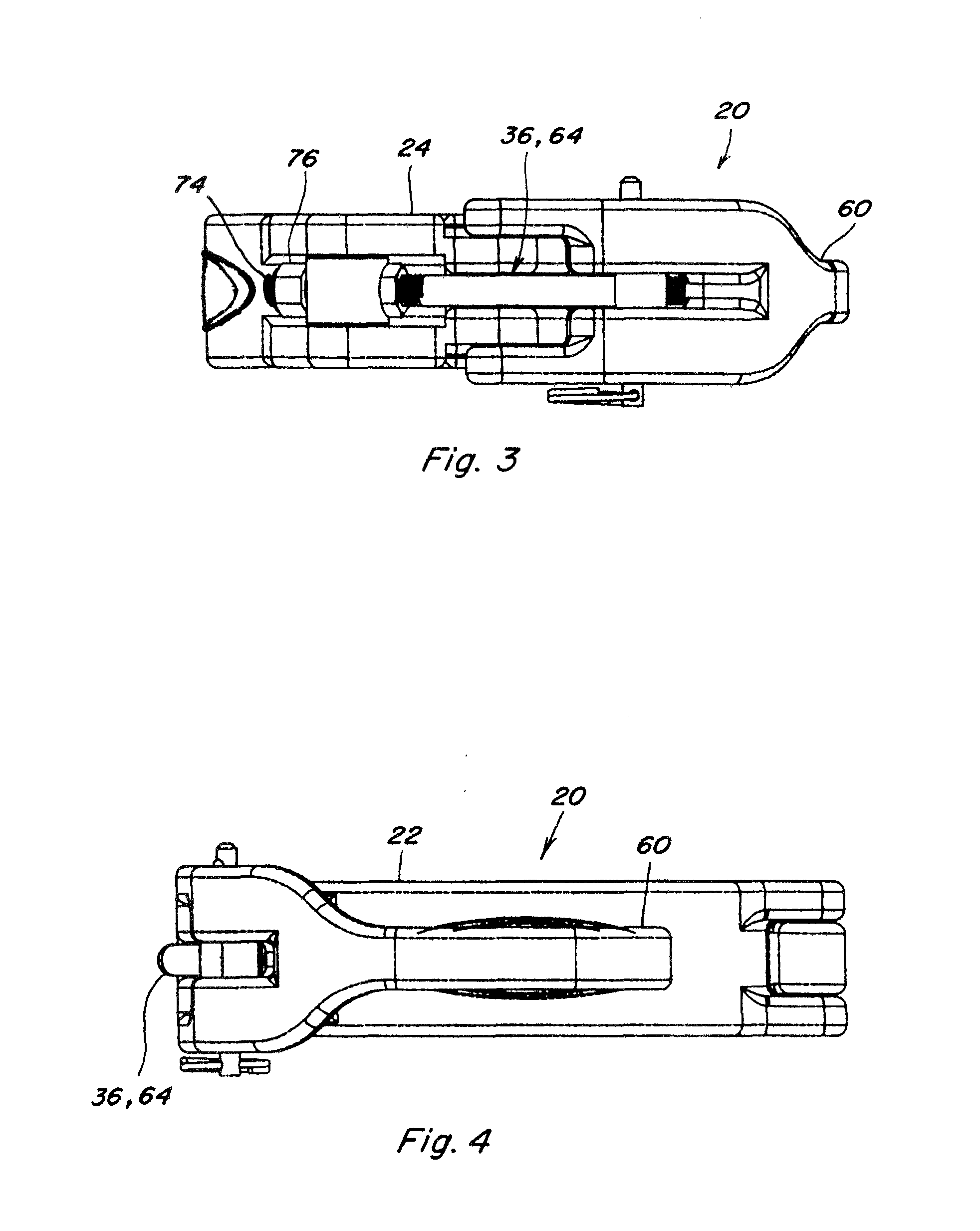
[0019]The clamping mechanism includes a handle pivotally connected with one of the semi-circular elements and to one end of a bail rod. The pivotal connection between to the handle and bail rod preferably comprises a clevis on the handle, with a pin extending through the clevis and the end of the bail rod. The portion of the end of the bail rod disposed in the clevis is configured to closely cooperate with the clevis, in particular, to have oppositely facing surfaces disposed in opposing relation to the sides of the clevis. This is advantageous, as it strengthens the joint so as to have the capability to withstand loading conditions, including tensile, compression, torsion and bending loads, anticipated to be encountered by the coupler during normal use.
[0020]As another preferred feature, each end of the bail rod is fixed or secured, at its pivotal connection to the handle or the other of the semi-circular elements, respectively, such that the bail rod can be pushed longitudinally, not just pulled as required for clamping. This is an advantageous feature, as it enables a manual force to be applied to the handle in the direction for unclamping the coupler, for also opening the coupler and releasing or breaking the coupler away from a pipe of fitting. This is advantageous, as it can eliminate need for striking the coupler with a hammer or the like to release it, and the possible damage that can result.
[0021]As still another preferred aspect of the invention, the bail rod of the clamping mechanism is configured so as to be adjustable in
effective length between the points of attachment to the handle and the other semi-circular element, to enable easily and precisely adjusting operation of the clamping mechanism and the tension in the bail rod when clamped. Here, the term “
effective length” denotes that portion of the length of the bail rod extending between the pivot points on the handle and on the other of the semi-circular elements.
[0023]As further preferred features of the invention, the handle has a generally C-shape when viewed from the side, including large
radius edges for improved ergonomics, and such that the free end of the handle curves back toward the coupler, to provide an opening sufficiently large for receiving a gloved hand, and for reducing locations where a person's hand can be pinched against the outer side of the coupler. This shape also makes it difficult to use leverage increasing tools on the handle for closing the coupler, which can damage or break the handle or other components of the coupler.


