Ring oscillator

a ring oscillator and ring technology, applied in the direction of pulse generation by logic circuits, pulse techniques, transistors, etc., can solve the problems of limited frequency of cyclic signals generated by oscillators, and oscillators are not capable, so as to suppress signal reflection and the effect of widening the line overall

Inactive Publication Date: 2010-12-30
ADVANTEST CORP
View PDF3 Cites 10 Cited by
  • Summary
  • Abstract
  • Description
  • Claims
  • Application Information

AI Technical Summary

Benefits of technology

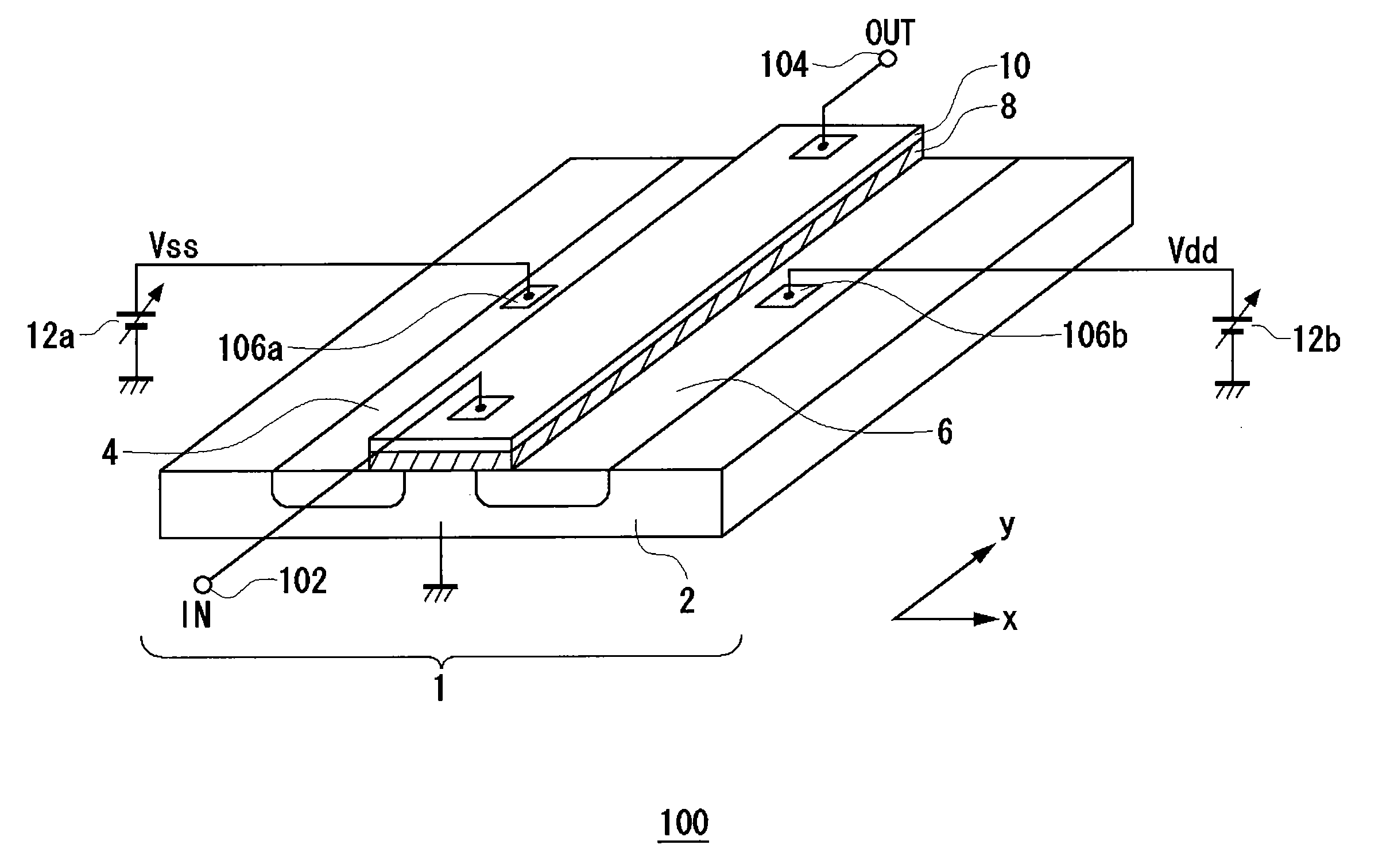
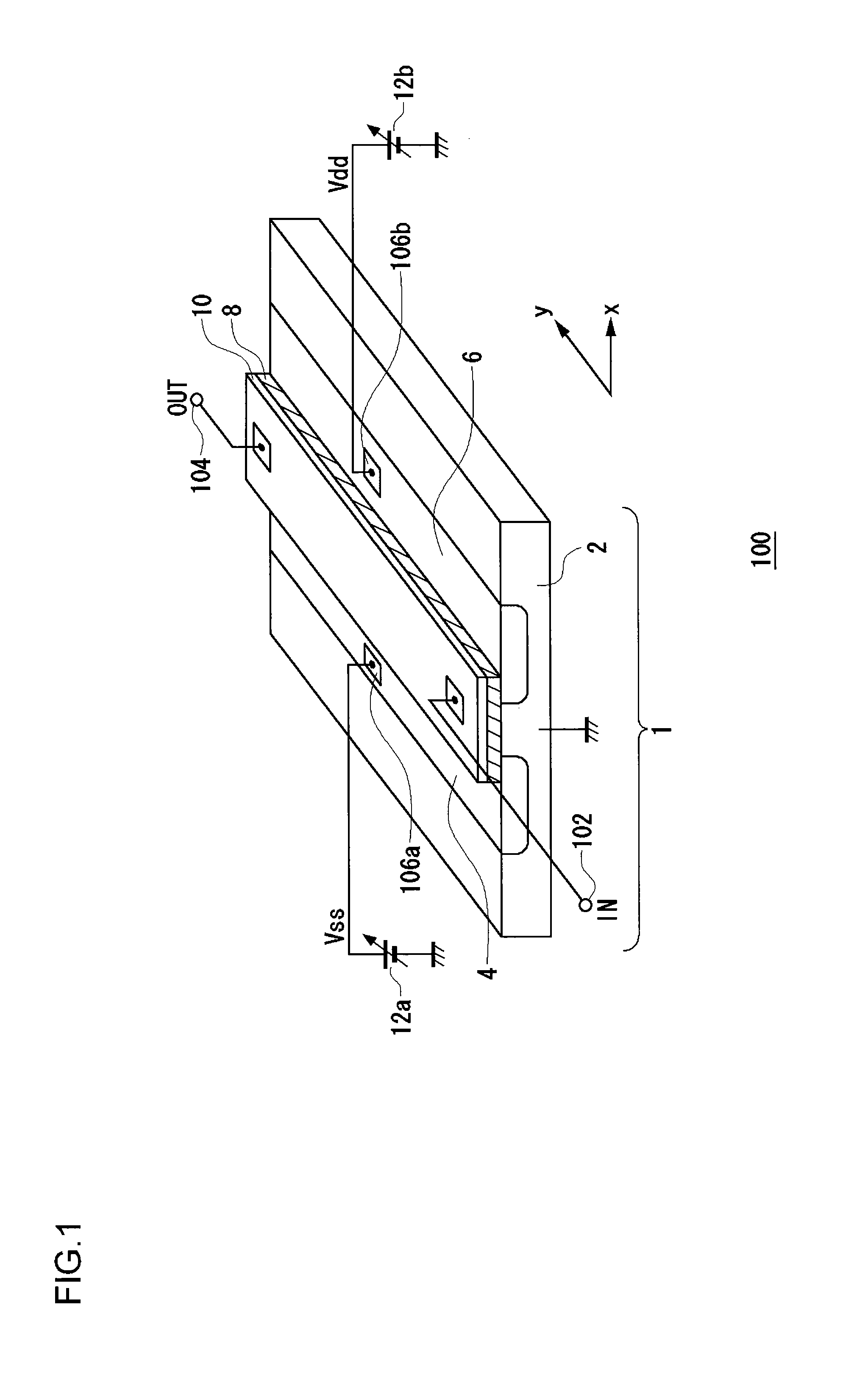
[0021]The gate-source capacitance and the gate-drain capacitance depend on the gate-source voltage and the gate-drain voltage, respectively. That is to say, the gate-source capacitance and the gate-drain capacitance each depend on the voltage level of the signal which is to be delayed and which propagates through the gate. Thus, by adjusting the voltage level of the signal to be delayed, such an arrangement is capable of controlling the delay time.
[0022]Also, the wiring width of the wiring line through which a signal is to be propagated may be varied in increments of the intervals between the multiple taps. The wiring length between adjacent taps may also be constant. In some cases, due to the effects of nonlinear properties of the wiring delay element itself, and of circuits connected to the delay circuit such as a circuit configured to apply a signal and a circuit configured to detect a signal, such an arrangement does not provide uniformity in the delay amount even in a case in which the wiring length is constant. In this case, by varying the wiring width, such an arrangement provides uniformity in the delay time.
[0023]Also, the overall wiring width of the line through which the signal is propagated may be constant irrespective of which tap is selected from among the taps arranged along the line. Such an arrangement is capable of suitably suppressing signal reflection due to branching of the signal.

Problems solved by technology

A ring oscillator having such a configuration has a problem in that the frequency of a cyclic signal generated thereby is limited by the delay time of the inverters.
That is to say, such a ring oscillator is not capable of generating a cyclic signal having a frequency or a pulse width that is shorter than the delay time of the inverters, which is a problem.

Method used


Image

  • Ring oscillator
  • Ring oscillator
  • Ring oscillator

Examples


Embodiment Construction

[0046]Description will be made below regarding preferred embodiments according to the present invention with reference to the drawings. The same or similar components, members, and processes are denoted by the same reference numerals, and redundant description thereof will be omitted as appropriate.

[0047]The embodiments have been described for exemplary purposes only, and are by no means intended to restrict the present invention. Also, it is not necessarily essential for the present invention that all the features or a combination thereof be provided as described in the embodiments.

[0048]In the present specification, the state represented by the phrase “the member A is connected to the member B” includes a state in which the member A is indirectly connected to the member B via another member that does not affect the electric connection therebetween, in addition to a state in which the member A is physically and directly connected to the member B. Similarly, the state represented by...


PUM


Abstract

Multiple multi-stage delay circuits each have n (n is an integer) output terminals. The multi-stage delay circuits each apply delay times to a corresponding input signal, and output, via n output terminals, n delayed signals to which different delay times have been applied. Multiple inverters invert the respective input signals. The multiple multi-stage delay circuits and multiple inverters are alternately connected in the form of a ring.

Description

[0001]This application is the U.S. National Stage of International Patent Application No. PCT / JP2009 / 000368 filed on Jan. 30, 2009, and claims priority thereto, and further claims priority to Japanese Patent Application No. 2008-040388 filed on Feb. 21, 2008 the disclosures of which is hereby incorporated by reference in its entirety.BACKGROUND OF THE INVENTION[0002]1. Field of the Invention[0003]The present invention relates to a ring oscillator.[0004]2. Description of the Related Art[0005]In order to provide a clock signal or a cyclic signal having a predetermined frequency, ring oscillators are employed in electronic circuits. A typical ring oscillator has a configuration in which multiple inverters (delay elements) are connected in the form of a ring.[0006]A ring oscillator having such a configuration has a problem in that the frequency of a cyclic signal generated thereby is limited by the delay time of the inverters. That is to say, such a ring oscillator is not capable of gen...

Claims


Application Information

Patent Timeline
Patent Type & Authority Applications(United States)
IPC IPC(8): H03K3/03
CPCH01L27/088H03K3/0315H03K5/1508H03K5/15046H03K5/14
Inventor YAMAMOTO, KAZUHIRO
Owner ADVANTEST CORP
Why Eureka
Try Eureka