Stereoscopic image displaying device, object proximity detecting device, and electronic apparatus

a stereoscopic image and display device technology, applied in the direction of electric digital data processing, instruments, computing, etc., can solve the problems of difficult to build the stereoscopic image display device in a small-sized electronic apparatus, difficult to decrease the thickness of the stereoscopic image displaying device, and inability to adjust the size and thickness, etc., to achieve the effect of easy formation, high responsiveness and reduced size and thickness

Active Publication Date: 2010-12-30
JAPAN DISPLAY INC
View PDF17 Cites 149 Cited by
  • Summary
  • Abstract
  • Description
  • Claims
  • Application Information

AI Technical Summary

Benefits of technology

[0021]The electronic apparatus having the above-described configuration is triggered to a display change or the like that is defined by an application or the like based on the detection result of the proximity sensor unit. At this time, similarly to the above-described stereoscopic image displaying device, the electronic apparatus detects the proximity of the detection target object to the outer surface based on the height (a distance from the outer surface) that is set based on the parallax information included in an input video signal. Accordingly, according to the electronic apparatus, there is no feeling of strangeness during the operation, and the responsiveness is high (a time until the display is

Problems solved by technology

In such a case, there is some dissatisfaction in the operation.
In addition, particularly, it is difficult to decrease the thickness of the stereosco

Method used


Image

  • Stereoscopic image displaying device, object proximity detecting device, and electronic apparatus
  • Stereoscopic image displaying device, object proximity detecting device, and electronic apparatus
  • Stereoscopic image displaying device, object proximity detecting device, and electronic apparatus

Examples


first embodiment

1. First Embodiment

Entire Configuration of Display Panel

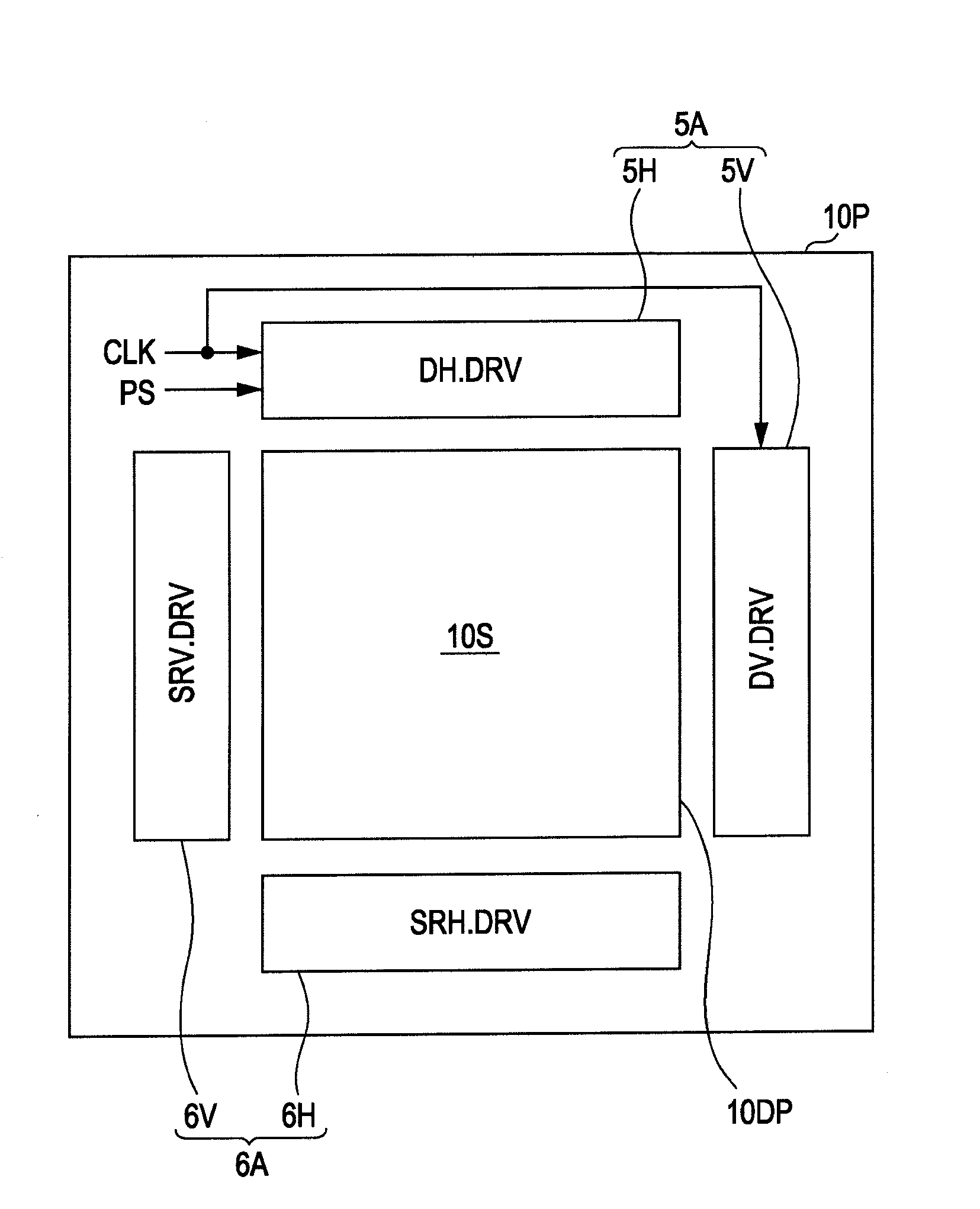
[0055]FIG. 1 is a block diagram showing a configuration example of a display panel included in a stereoscopic image display panel according to a first embodiment of the present invention. Although a display type, not shown in the figure, is different, and the type of a proximity sensor or a built-in type is different, the configuration shown in FIG. 1 is commonly used by a stereoscopic image displaying device according to other embodiments of the present invention.

[0056]A display panel 10P shown in FIG. 1 includes a display unit 10DP having an external attachment-type proximity sensor, to which an electrostatic capacitance-type proximity sensor unit is added, attached to the surface thereof and peripheral circuits thereof. The outermost surface of the display panel 10P is an outer surface 10S that a detection target (a fingertip, a stylus pen, or the like) according to an embodiment of the present invention approaches. The peri...

second embodiment

2. Second Embodiment

[0107]The second embodiment is an example in which an electrostatic capacitance-type sensor is built in a display panel. The second embodiment relates to a configuration of a partially-built-in type in which a driving electrode of the display panel is commonly used as a sensor driving electrode. There is only a structural difference between the first and second embodiments, and other operations, detection techniques, and the like are the same as those of the first embodiment. Thus, hereinafter, only the difference will be described.

[0108]FIG. 10 is a schematic cross-sectional view of a display panel according to this embodiment. In the configuration shown in FIG. 10, the proximity sensor panel 60P (FIG. 2) is omitted, and an optical modulation panel denoted by reference sign 52 has the function of the sensor. Hereinafter, this optical modulation panel is referred to as a sensor built-in panel 52.

[0109]In FIGS. 11A to 11C, detailed cross-sectional views and a plan...

third embodiment

3. Third Embodiment

[0123]As a type in which the sensitivity of the sensor can be easily improved in accordance with advance of semiconductor devices and which has relatively high sensitivity and can be easily built in a display panel, there is an optical type. This embodiment relates to a stereoscopic image displaying device having an optical sensor disposed inside the display panel. In the description below, particularly the circuit configuration of the proximity sensor and other aspects that are different from those of the electrostatic capacitance type described in the first and second embodiments will be described. Accordingly, there is no difference between the embodiments in the structure of the parallax barrier (PV), the basic of the stereoscopic image displaying operation, and the basic (particularly, the relationship between the sensitivity of detection and the imaging height) of the object detecting operation described above except for the detection principles of light and...


PUM


Abstract

A stereoscopic image displaying device includes an outer surface that a detection target object approaches; a stereoscopic image generating unit that generates a three-dimensional stereoscopic image based on an input video signal, and a proximity sensor unit that is disposed on a side of the outer surface that is opposite to a side that the detection target object approaches and detects proximity of the detection target object to the outer surface based on a height that is a distance from the outer surface and is set based on parallax information included in the video signal.

Description

[0001]The present application claims priority to Japanese Patent Application JP 2009-1555376 filed in the Japanese Patent Office on Jun. 30, 2009, the entire content of which is hereby incorporated by reference.BACKGROUND OF THE INVENTION[0002]1. Field of the Invention[0003]The present invention relates to a stereoscopic image displaying device that can display a stereoscopic image and has a proximity sensing function for detecting an operation on the stereoscopic image and the like and an electronic apparatus that has the function of displaying a stereoscopic image. In addition, the present invention relates to an object proximity detecting device capable of detecting proximity of an object.[0004]2. Description of the Related Art[0005]Recently, the number of liquid crystal display devices for mobile use that use touch panels for input functions has become large. In such a device, a touch panel of the electrostatic capacitance type, the resistance film type, or the optical type is d...

Claims


Application Information

Patent Timeline
IPC IPC(8): H04N13/04G02B30/27G02B30/30
CPCG02B27/2214G06F3/0412G06F3/042H04N13/0456H04N13/0409H04N13/0411H04N13/0454G06F3/044H04N13/31H04N13/312H04N13/359H04N13/361G02B30/27G06F3/0446G06F3/0445G02B30/30
Inventor OHYAMA, TSUYOSHITANAKA, TSUTOMUIMAI, MASATO
Owner JAPAN DISPLAY INC
Why Eureka
Try Eureka