
Hierarchical light intensity control in light projector

a light projector and light intensity control technology, applied in the direction of instruments, lighting and heating apparatus, color signal processing circuits, etc., can solve the problems of stereoscopic imaging problems even more pronounced, difficult to maintain the high quality demands of digital cinema,

Active Publication Date: 2010-12-30
IMAX THEATERS INT
View PDF40 Cites 30 Cited by
  • Summary
  • Abstract
  • Description
  • Claims
  • Application Information

AI Technical Summary

Benefits of technology

[0021]It is an advantage of the present invention that it allows automatic fine-tuning adjustment of output intensity on multiple levels: laser, color channel, left / right stereoscopic, and white point, to compensate for drift and component aging or failure.

Problems solved by technology

However, with LCD components it can be difficult to maintain the high quality demands of digital cinema, particularly with regard to color and contrast, since the high thermal load of high brightness projection affects polarization qualities of these devices.
The polarizer is required, since the DLP is not inherently designed to maintain the polarization of the input light, which is generally unpolarized, as the window of the device package depolarizes due to stress induced birefringence.
One problem raised by the use of solid-state light sources relates to achieving a suitable balance of the light output from each color channel.
However, factors such as component aging and drift can degrade the initial color adjustment so that the color balance is no longer acceptable.
This problem is even more pronounced for stereoscopic imaging.
Failure to achieve a compatible intensity of color channels for left- and right-eye images can render the projected stereoscopic images as unappealing or, at worst, as visually disturbing to the viewer.

Method used


Image

  • Hierarchical light intensity control in light projector
  • Hierarchical light intensity control in light projector
  • Hierarchical light intensity control in light projector

Examples


Embodiment Construction

[0041]The present description is directed in particular to elements forming part of, or cooperating more directly with, apparatus in accordance with the invention. It is to be understood that elements not specifically shown or described may take various forms well known to those skilled in the art.

[0042]Figures shown and described herein are provided to illustrate principles of operation according to the present invention and are not drawn with intent to show actual size or scale. Because of the relative dimensions of the component parts for the laser array of the present invention, some exaggeration is necessary in order to emphasize basic structure, shape, and principles of operation.

[0043]The invention is inclusive of combinations of the embodiments described herein. References to “a particular embodiment” and the like refer to features that are present in at least one embodiment of the invention. Separate references to “an embodiment” or “particular embodiments” or the like do n...


PUM


Abstract

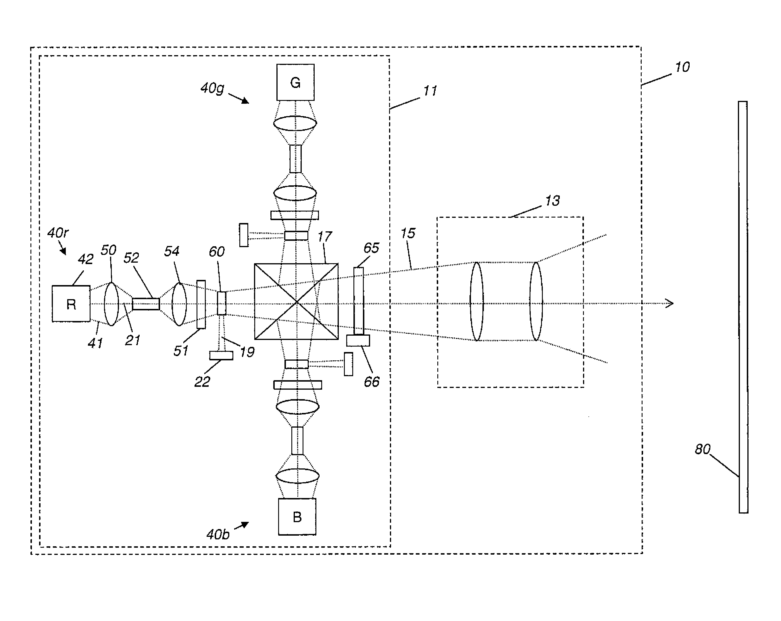
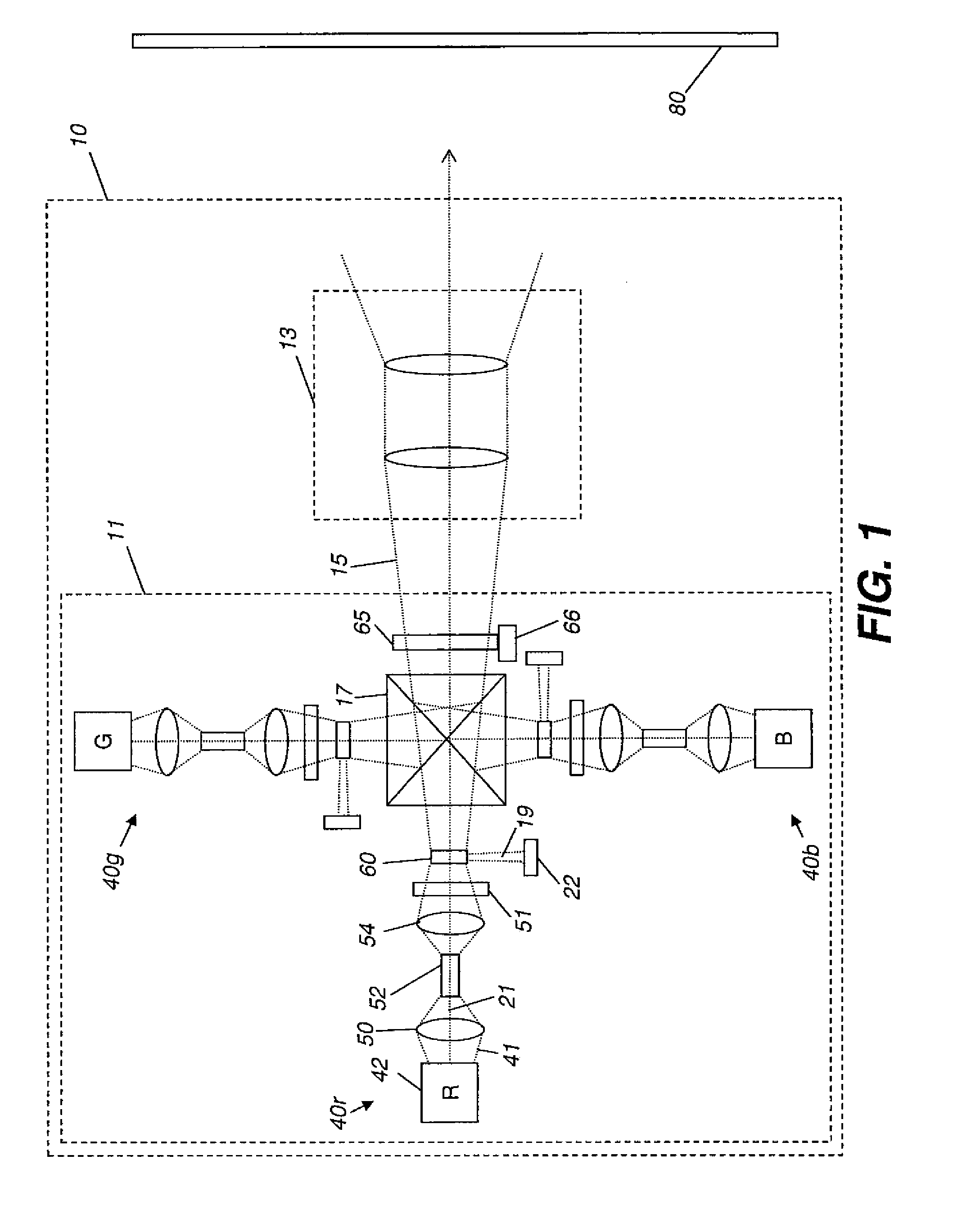
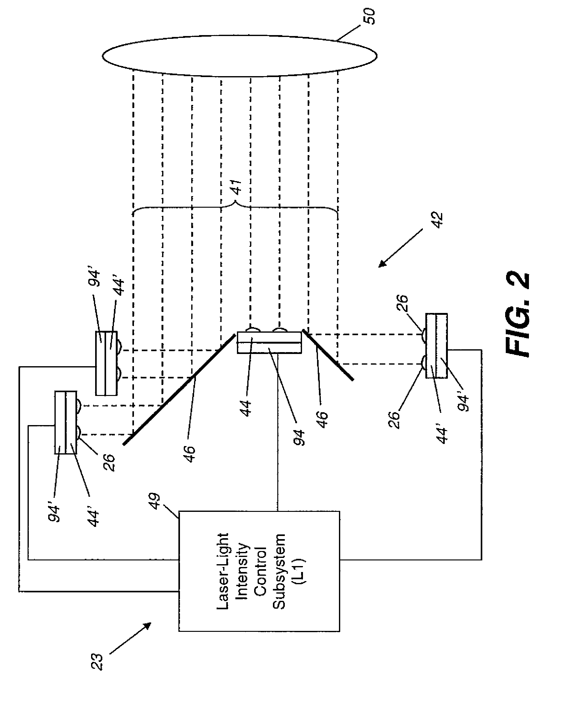
In a light projection system, potentially hierarchical levels of light intensity control ensure proper laser-light output intensity, color channel intensity, white point, left / right image intensity balancing, or combinations thereof The light projection system can include a light intensity sensor in an image path, in a light-source subsystem light-dump path, in a light-modulation subsystem light-dump path, in a position to measure light leaked from optical components, or combinations thereof.

Description

CROSS REFERENCE TO RELATED APPLICATIONS[0001]This application is filed concurrently with and has related subject matter to:[0002]U.S. patent application Ser. No. ______, titled “Stereoscopic Image Intensity Balancing in Light Projector”, with Barry Silverstein as the first named inventor and an attorney docket number of 95598;[0003]U.S. patent application Ser. No. ______, titled “Image Path Light Intensity Sensing in Light Projector”, with Barry Silverstein as the first named inventor and an attorney docket number of 95600;[0004]U.S. patent application Ser. No. ______, titled “Dump Path Light Intensity Sensing in Light Projector”, with Barry Silverstein as the first named inventor and an attorney docket number of 95601; and[0005]U.S. patent application Ser. No. ______, titled “Leakage Light Intensity Sensing in Light Projector”, with Barry Silverstein as the first named inventor and an attorney docket number of 95602,[0006]each of which is incorporated herein by reference in its ent...

Claims


Application Information

Patent Timeline
Patent Type & Authority Applications(United States)
IPC IPC(8): G03B21/00G09G5/02G02B30/25
CPCH04N9/3129H04N9/73H04N9/3155
Inventor SILVERSTEIN, BARRY D.COREY, RICHARD P.DOWE, DAVID R.
Owner IMAX THEATERS INT
Learn More