Method and apparatus for detecting a boundary in an environment of an object

a technology of object environment and boundary detection, applied in the field of method and apparatus for detecting boundary in object environment, can solve the problem of huge computation effort and achieve the effects of reducing the distance between neighboring region of interest windows, reducing the size/length of the region of interest window, and improving reliability and accuracy

Active Publication Date: 2019-07-25
CONTINENTAL AUTOMOTIVE GMBH
View PDF0 Cites 3 Cited by
  • Summary
  • Abstract
  • Description
  • Claims
  • Application Information

AI Technical Summary

Benefits of technology

[0024]In a possible embodiment, the orientation of the further region of interest window is only adapted, if a difference between the orientation of the current region of interest window and the desired orientation of the next region of interest window is less than a predetermined threshold value. By limiting the acquisition of the orientation for the region of interest window to a particular threshold value, the reliability and the accuracy may be further improved. In particular, failures of outliners to an inaccuracy or an error in the detection of the environment may be compensated. Especially, the threshold value for limiting the takeover of the orientation for the region of interest window may be dynamically adapted. For example, the threshold value may be adapted depending on previous changes of the orientation for the region of interest windows. Hence, if only small changes occur in the orientation between successive region of interest windows, it may be assumed, for instance, that the boundary relates to an almost straight road, and consequently no sharp curves will occur. However, if higher changes occur in the boundary, it may be assumed that also higher changes in the orientation may be possible for the successive region of interest windows.
[0025]In a possible embodiment, a length of a region of interest window and / or a distance between neighboring region of interest windows is adapted based on deviation of the orientation between neighboring region of interest windows. For example, if the orientation between neighboring region of interest windows changes more than a predetermined threshold value, a road boundary may be considered to be curvy. In this case, the size / length of the region of interest windows may be reduced or the distance between neighboring region of interest windows may be reduced. Hence, the accuracy can be increased. Otherwise, if the orientation between neighboring region of interest windows does not change more than the predetermined threshold value, the road boundary to be considered to be less curvy and thus, the size / length of region of interest windows may be increased and / or the distance between neighboring region of interest windows may be increased.

Problems solved by technology

However, the determination of the free space in the surrounding of a vehicle and in particular the identification of a boundary between a free and occupied space requires huge computation effort and is error-prone.

Method used


Image

  • Method and apparatus for detecting a boundary in an environment of an object
  • Method and apparatus for detecting a boundary in an environment of an object

Examples


Embodiment Construction

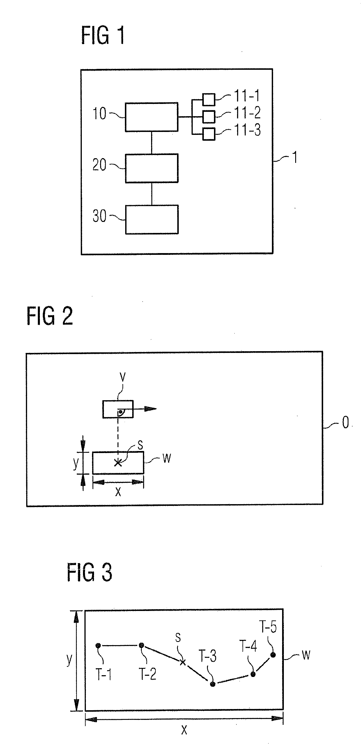
[0038]FIG. 1 shows a block diagram of an apparatus 1 for detecting a boundary. The apparatus 1 for detecting a boundary comprises an occupancy detector 10, a boundary detector 20 and boundary processor 30. The occupancy detector 10 may comprise optical sensors 10-1, a radar sensor 10-2 and / or an ultrasonic sensor 10-3. However, it is understood that any other sensor for scanning the environment and providing data related to the occupancy in the environment may be also possible. The sensors 10-i may scan the environment and provide sensor data which can be analyzed. For instance, occupancy detector 10 may receive the sensor data from the sensors 10-i and process the sensor data in order to generate an occupancy grid. The occupancy grid may be, for example, a two-dimensional representation for specifying at each grid cell of the occupancy grid a probability for a degree of occupancy. For example, the occupancy grid may be a two-dimensional matrix where each matrix element represents a...


PUM


Abstract

A detection of a boundary in an environment. For this purpose, information of an occupancy grid is used, wherein the occupancy grid provides information about the probability of occupancy in the environment. Upon detecting a starting transition point between a free and an occupied grid cell in the occupancy grid, a region of interest window surrounding the starting transition point is analyzed to identify further transition points. The identified transition points are combined to one or more polygon chain. After the analysis of the boundary is performed within the region of interest, successive regions of interest may be analyzed. For this purpose, the successive regions of interest are determined based on the transition points and/or the boundary information of a current region of interest window.

Description

CROSS REFERENCE TO RELATED APPLICATION[0001]This application claims priority to EP Application No. EP 18152685, filed Jan. 22, 2018, the contents of such application being incorporated by reference herein.FIELD OF THE INVENTION[0002]The present invention relates to a method and an apparatus for detecting a boundary in an environment of an object. The present invention further relates to an advanced driver assistance system, an autonomous driving vehicle and an industrial robot system.BACKGROUND OF THE INVENTION[0003]Although applicable in principle to any system applying free space detection, the present invention and its underlying problem will be hereinafter described in connection with an advanced driver assistance system.[0004]Modern vehicles like cars or trucks usually comprise driver assistance systems which may support the driver of a vehicle when performing driving maneuvers. For performing automatic driving maneuvers, a free space in the surrounding of a vehicle has to be d...

Claims


Application Information

Patent Timeline
Patent Type & Authority Applications(United States)
IPC IPC(8): G06K9/00G06K9/32G06T7/70G06T7/11G05D1/00
CPCG06K9/00798G06K9/3233G06T7/70G06T7/11G05D1/0088G06T2207/30256G05D2201/0213G01C21/34G01S13/931G05D1/0231G05D1/0274B60W40/04G06V20/586B60W30/00G06V20/588
Inventor CHAVALI, POTHURAJUONKARAPPA, NAVEENWISCHER, GERRIT
Owner CONTINENTAL AUTOMOTIVE GMBH
Why Eureka
Try Eureka