Fluorescent wheel, light source device and projector

a technology of light source device and fluorescence wheel, which is applied in the direction of instruments, lighting and heating apparatus, spectral modifiers, etc., can solve the problems of low fluorescence use efficiency, difficult use of light source in electronic devices whose sizes have been reduced, and emitted fluorescen

Active Publication Date: 2010-12-30
CASIO COMPUTER CO LTD
View PDF6 Cites 89 Cited by
  • Summary
  • Abstract
  • Description
  • Claims
  • Application Information

AI Technical Summary

Problems solved by technology

Thus, these light sources are difficult to be used in electronic devices whose sizes have been reduced recently.
However, in the above proposals, most of the fluorescence emitted in directions substantially parallel to the fluorescence emission surface of the fluorescent layer is useless and hence the use efficiency of the fluorescence is low.

Method used


Image

  • Fluorescent wheel, light source device and projector
  • Fluorescent wheel, light source device and projector
  • Fluorescent wheel, light source device and projector

Examples


Embodiment Construction

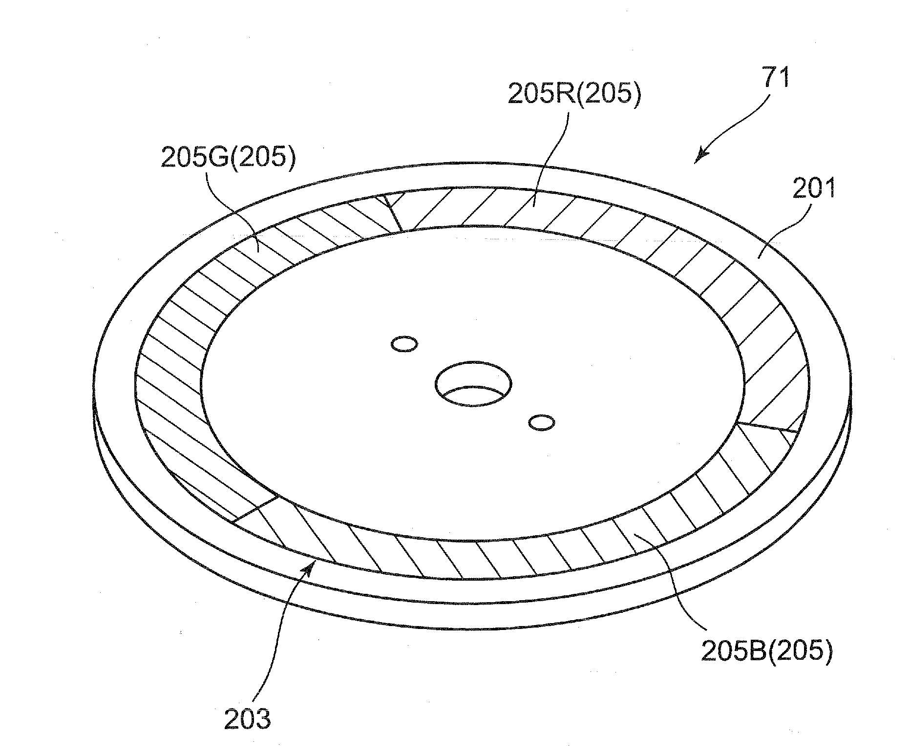
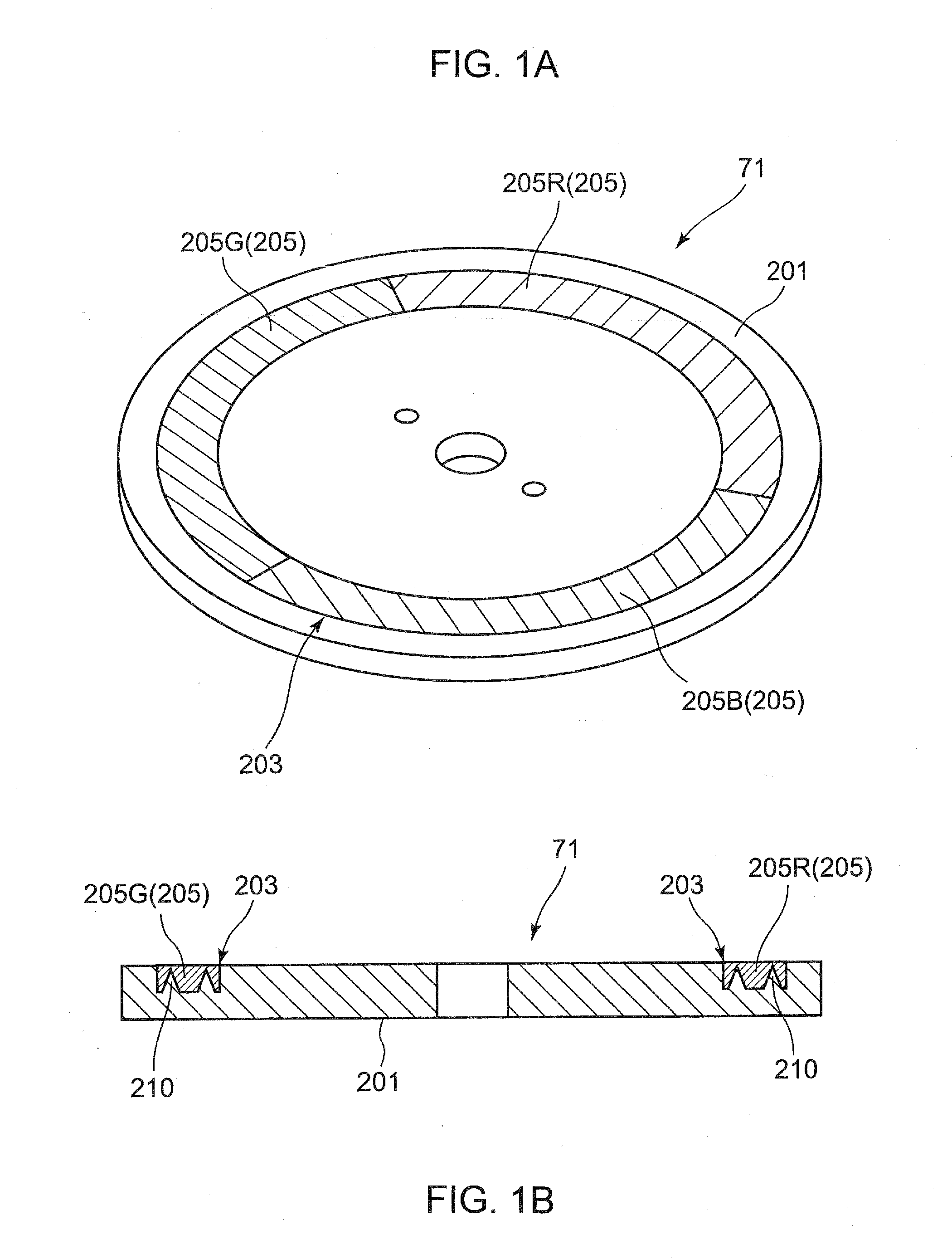
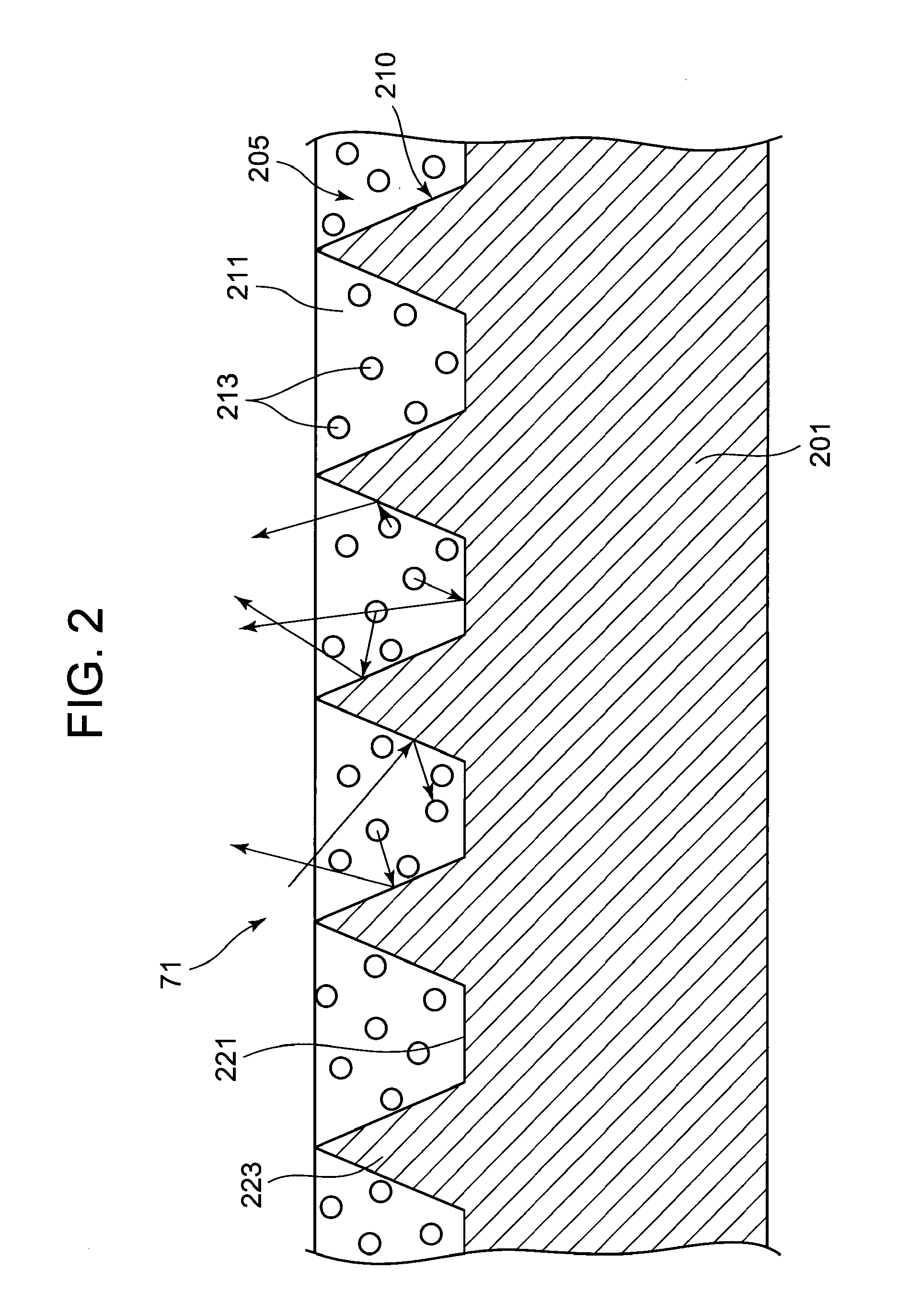
[0038]As shown in FIGS. 1A and B, a fluorescent body device, or more particularly a fluorescent wheel 71, of this embodiment comprises a base disc 201 with a fluorescent layer 205 imbedded within a ring-like groove 203 provided concentric within the base disc close to its outer periphery. When irradiated with exciting light, fluorescent substances 213 contained in the fluorescent layer 205 are excited, thereby emitting fluorescence of a predetermined wavelength band. The fluorescence is directly emitted outward from the outer surface of the fluorescent layer 205 or reflected, for example, by a bottom of the groove 203 and then emitted outward from the outer surface of the fluorescent layer 205.

[0039]The base disc 201 is made of a metal material such as silver of high reflectance. The base disc 201 has a central opening through which a rotational shaft 76 (FIG. 11) connects the base disc 201 and a motor 73 (FIGS. 11 and 14) for rotation of the disc. The inner surface of the ring-like...


PUM


Abstract

A fluorescent wheel comprising a base with a reflective surface and a flat bottom surface, and a fluorescent layer disposed on the reflective surface of the base such that the reflective surface of the base directs, outward from the wheel, fluorescence emitted from the fluorescent layer due to its excitation by exciting light. The reflective surface of the base has an array of minute reflective structures formed thereon so as to reflect, outward from the reflective surface, fluorescence emitted substantially parallel to the flat bottom surface of the base from the fluorescent layer.

Description

[0001]This application is based on Japanese Patent Applications No. 2009-155478 filed on Jun. 30, 2009 and including specification, claims, drawings and summary. The disclosure of the above Japanese patent applications is incorporated herein by reference in its entirety.BACKGROUND OF THE INVENTION[0002]1. Field of the Invention[0003]The present invention relates to a fluorescent body device, and more particularly to a fluorescent wheel with a fluorescent layer thereon which is rotated by a motor to emit selected fluorescence due to irradiation of exciting light of a predetermined wavelength, a light source device including the fluorescent wheel, and a projector which includes the light source device and which projects a color image onto a display screen.[0004]2. Description of the Related Art[0005]Recently, in various electronic devices, light sources are used which include a light emitting diode or a laser diode, or emits organic electro-luminescence or fluorescence. The light sour...

Claims


Application Information

Patent Timeline
Patent Type & Authority Applications(United States)
IPC IPC(8): G03B21/14F21V9/16
CPCG03B21/14F21V13/08G03B21/204
Inventor MASUDA, HIROKI
Owner CASIO COMPUTER CO LTD
Why Eureka
Try Eureka