Modular microscope construction

a microscope and module technology, applied in the field of modules, can solve the problems of manufacturing and high cost of customizing the microscope system, and manufacturers or users cannot allow users to customize the microscope system,

Inactive Publication Date: 2010-12-30
BIO RAD LAB INC
View PDF17 Cites 23 Cited by
  • Summary
  • Abstract
  • Description
  • Claims
  • Application Information

AI Technical Summary

Benefits of technology

[0008]In yet another embodiment, the lens module can have a motorized focus module controlled by the control module or external general use computer to control or correct the focus of the lens module. In other embodiments, the illumination module comprises LEDs that can be configured to provide dark field or bright field illumination. The illumination module can switch between dark field and light field illumination using electronic switch. In other words, the illumination module can switch between dark field and light field illumination with no moving parts, and thus no extraneous physical vibrations to the illumination module or the modular microscope.

Problems solved by technology

Current microscopes do not allow for manufacturers or users to customize the microscope system to the exact needs of the user.
In such microscopes, manufacturing and, consequently, purchasing customized microscopes can be extremely expensive.
Once the custom microscope is manufactured according to contemporary designs and methods, changing or adding to the configuration of the custom microscope is often prohibitively expensive and impractical.
In addition, digital microscopes currently on the market have no way to control how users use the digital microscope or the images produced by the digital microscope.
Such limitations prevent manufacturers from customizing low cost off-the-shelf turnkey digital microscopes and controlling how the digital microscopes are used by a client computer or other computing device or subsequently protecting the images captured using the digital microscope.
Additionally, manufacturers and users alike have no automatic way of coupling digital rights management to the images produced with their digital microscopes.
As such manufacturers have no way to encourage or force users to purchase and use software and hardware in combinations intended by the manufacturer or seller.

Method used


Image

  • Modular microscope construction
  • Modular microscope construction
  • Modular microscope construction

Examples


Embodiment Construction

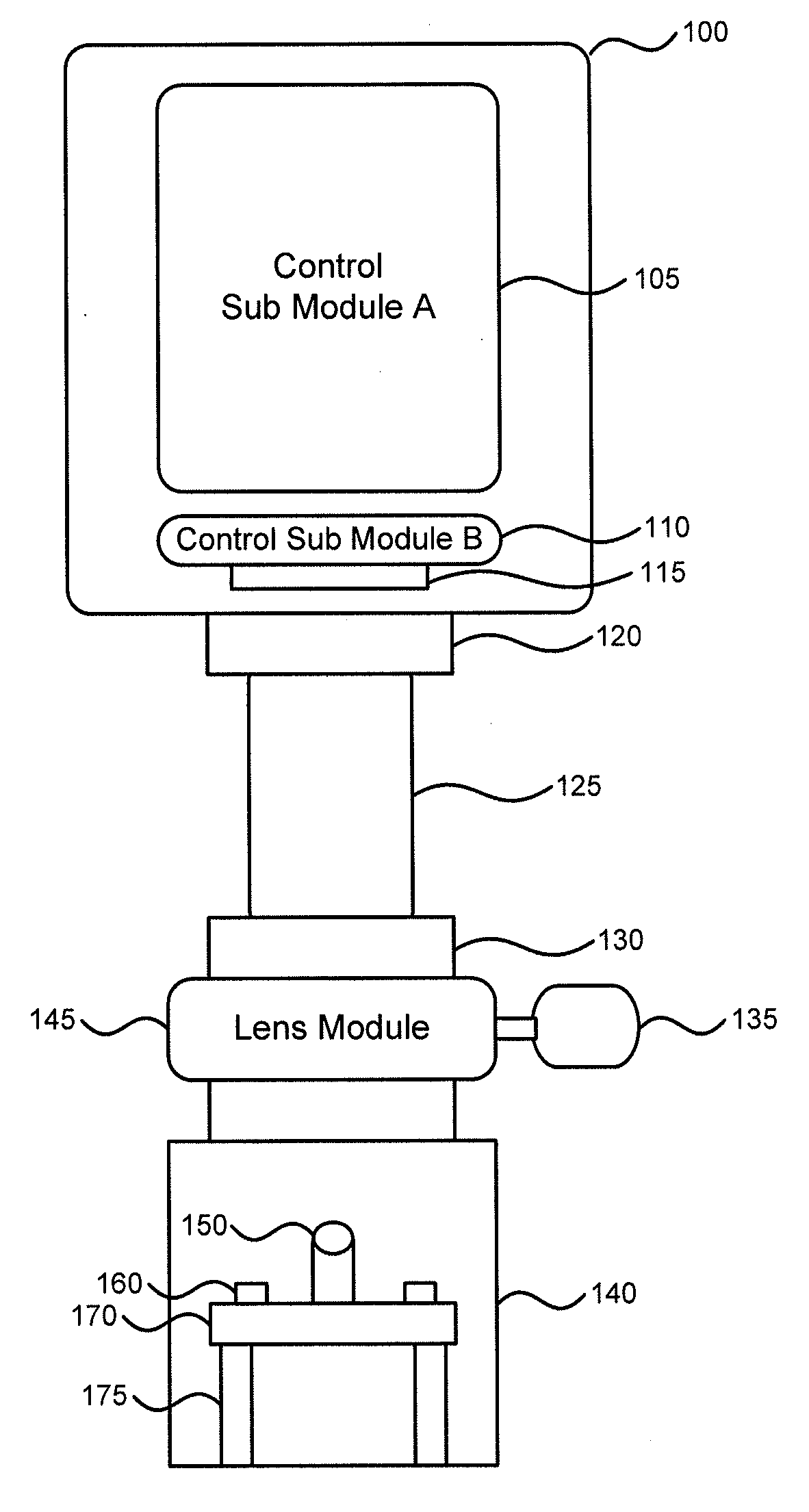
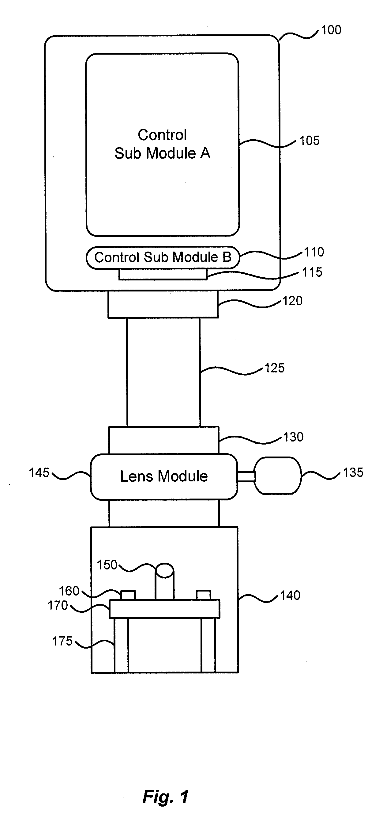
[0015]FIG. 1 depicts a schematic of a modular microscope according to one embodiment of the present invention. The modular microscope can include several main components; control module 100, lens module 125 and illumination module 140 and imager module (not shown).

[0016]In FIG. 1, one possible embodiment of the control module is depicted with control sub module A 105 and control sub module B 110. In other embodiments, the control module 100 can include these and more control sub modules. In such embodiments, the presence of multiple control sub modules allows various functionalities of the control module 100 to be isolated or assigned to one or more of the control sub modules. This is particularly helpful for isolating the security, operational and other functionality amongst the various control sub modules.

[0017]Although the modules of modular microscope depicted in FIG. 1 will be described as an exemplary embodiment, each module including specific elements and capable of specific ...


PUM


Abstract

A system, apparatus and method for using modular microscopes is disclosed. Connecting the housings of the individual microscope modules provide the structural framework of the modular microscope. Furthermore, the modular microscope can include specialized software, the distribution and use of which can be controlled using security keys or identifiers stored on one or more of the microscope modules. The security keys and identifiers can be based on calibration data associated with the physical, electrical, or optical properties of one of more of the modules. The illumination modules disclosed provide for selectable wavelengths and controllable levels of output illumination for both bright field and dark field illumination.

Description

CROSS-REFERENCES TO RELATED APPLICATIONS[0001]This application claims priority to U.S. Provisional Patent Application No. 61 / 220,776, filed on Jun. 26, 2009, entitled Modular Microscope Construction. This provisional patent application is incorporated herein by reference in its entirety for all purposes.BACKGROUND OF THE INVENTION[0002]Current microscopes do not allow for manufacturers or users to customize the microscope system to the exact needs of the user. Most low cost solutions incorporate a housing or structural backbone onto which the components of the microscope are permanently built. In such microscopes, manufacturing and, consequently, purchasing customized microscopes can be extremely expensive. Once the custom microscope is manufactured according to contemporary designs and methods, changing or adding to the configuration of the custom microscope is often prohibitively expensive and impractical. As such, most current microscopes, if customized at all, are purchased and ...

Claims


Application Information

Patent Timeline
Patent Type & Authority Applications(United States)
IPC IPC(8): G02B21/06
CPCG02B21/125G02B21/16G02B21/24G02B21/365G02B21/06
Inventor GRIFFIN, MICHAELCHU, DANIEL YUE MANMCCOLLUM, TOM
Owner BIO RAD LAB INC
Why Eureka
Try Eureka