Multiple antenna spatial multiplexing optimal detection

a multi-antenna and optimal detection technology, applied in diversity/multi-antenna systems, amplitude demodulation, baseband system details, etc., can solve the problem of increasing the computational complexity of the applicable receiver, adding a great deal of complexity to any mimo system, and high cost for an optimal solution

Active Publication Date: 2010-12-30
HONG KONG APPLIED SCI & TECH RES INST
View PDF5 Cites 15 Cited by
  • Summary
  • Abstract
  • Description
  • Claims
  • Application Information

AI Technical Summary

Benefits of technology

[0014]The foregoing has outlined rather broadly the features and technical advantages of the present teachings in order that the detailed description that follows may be better understood. Additional features and advantages of the teachings herein will be described hereinafter which form the subject of the claims. It should be appreciated by those skilled in the art that the conception and specific embodiment disclosed may be readily utilized as a basis for modifying or designing other structures for carrying out the same purposes of the present teachings. It should also be realized by those skilled in the art that such equivalent constructions do not depart from the spirit and scope of the teachings as set forth in the appended claims. The novel features which are believed to be characteristic of the teachings herein, both as to its organization and method of operation, together with further objects and advantages will be better understood from the following description when considered in connection with the accompanying figures. It is to be expressly understood, however, that each of the figures is provided for the purpose of illustration and description only and is not intended as a definition of the limits of the present teachings.

Problems solved by technology

However, it is the MIMO detection process, at MIMO detection unit 103, that typically adds a great deal of complexity to any MIMO system.
However, as noted above, examination of such a large number of possible combinations, especially in higher ordered modulation rates, raises the computational complexity of the applicable receiver.
As expected, though, the cost for an optimal solution is high computational complexity.
Many of the existing detection techniques considered practical for real world application are sub-optimal because they simply cannot guarantee detection of both required distance variables, and, as such, cannot produce an optimal solution every time.
The resulting reduction in combinations that are examined greatly simplifies the computational requirements but does so at the cost of detection quality.
Another aspect of computational complexity found in the LSD detection methodology is its use of tree structures to represent constellation signals.
However, the process used simply to parse these tree structures provides a great deal of additional complexity to the receiver.
However, even the described process of the '813 application admittedly sacrifices some optimality in order to reduce computational complexity.

Method used


Image

  • Multiple antenna spatial multiplexing optimal detection
  • Multiple antenna spatial multiplexing optimal detection
  • Multiple antenna spatial multiplexing optimal detection

Examples


Embodiment Construction

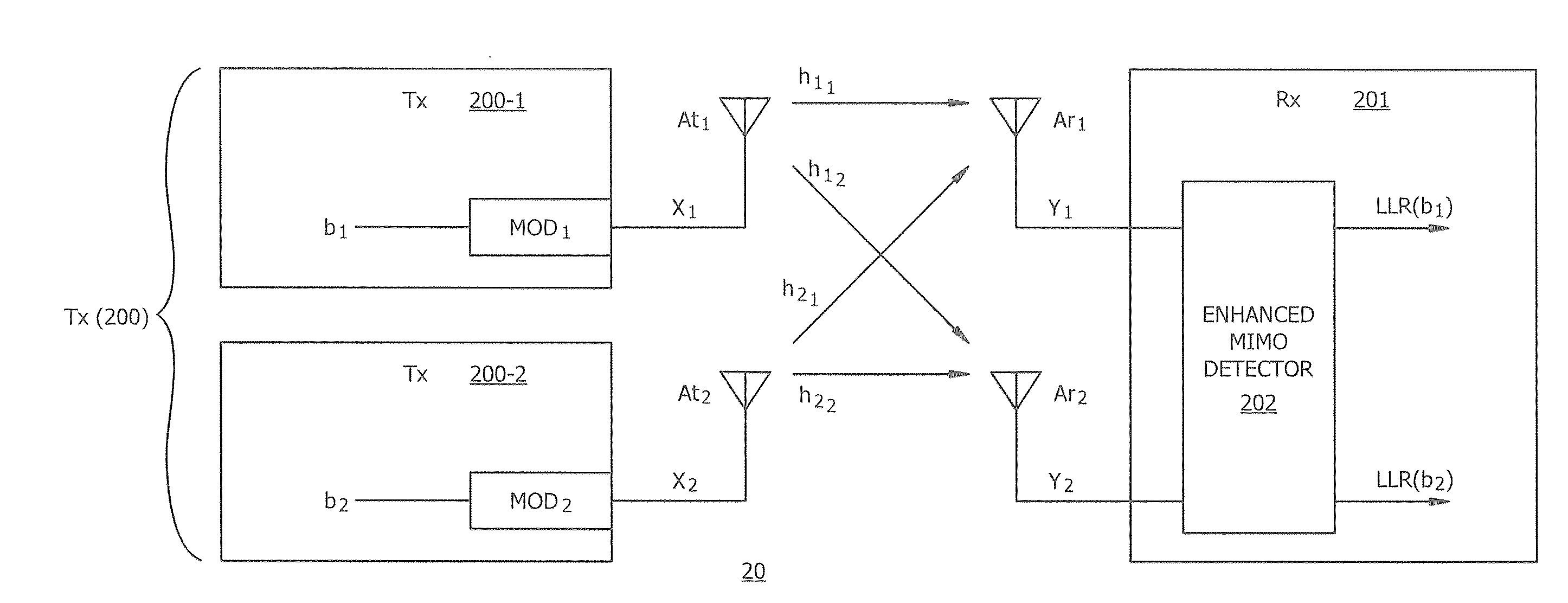
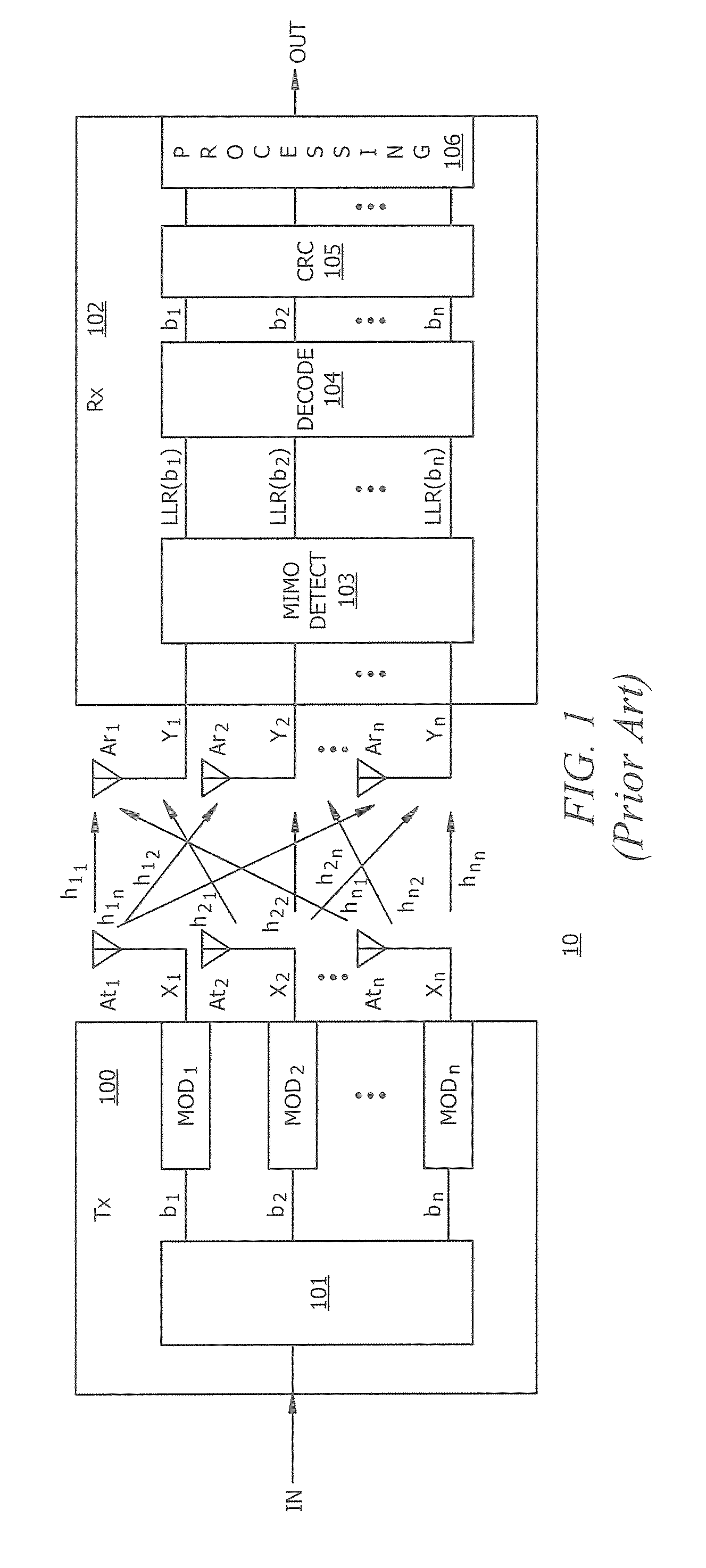
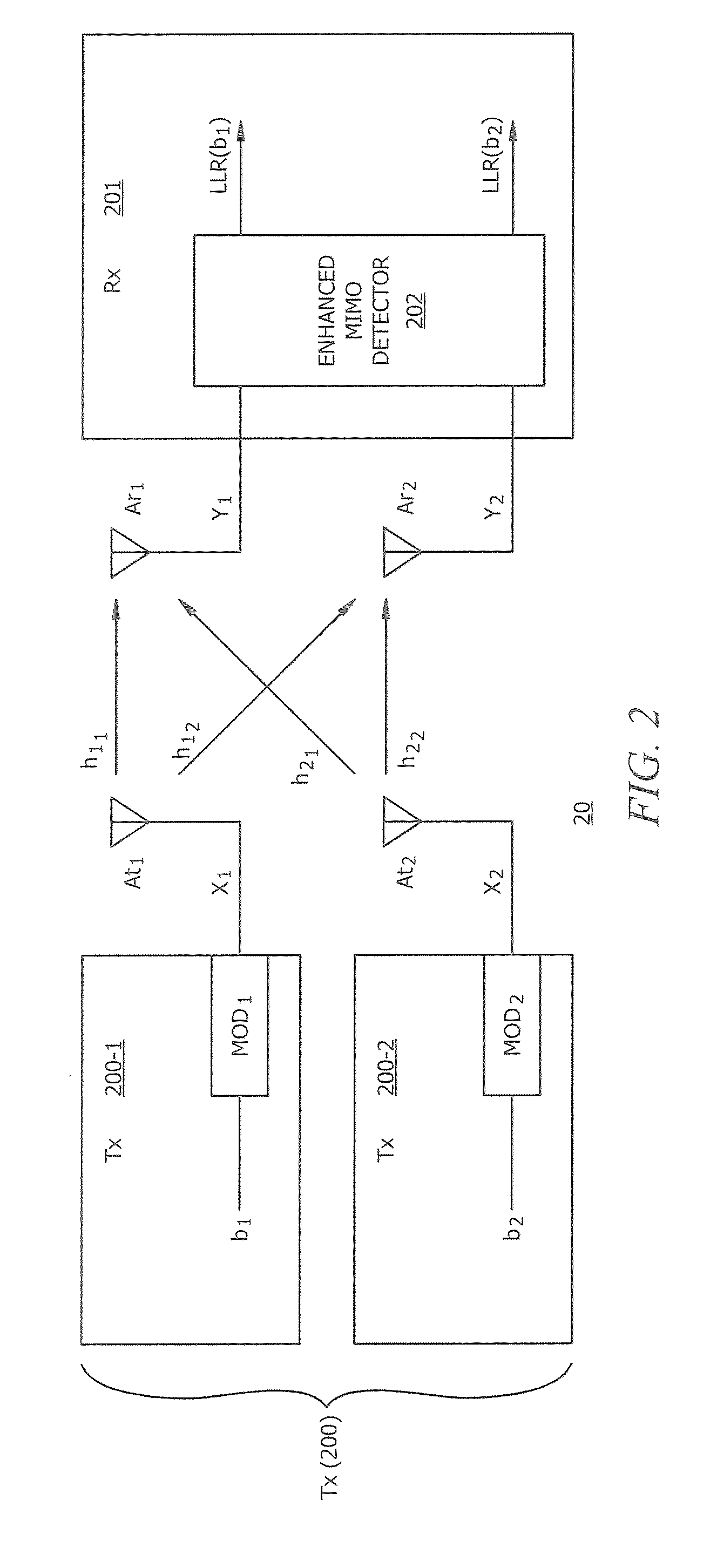
[0026]FIG. 2 is a block diagram illustrating spatial multiplexing MIMO wireless system 20 configured according to one embodiment of the present teachings. Transmitter 200 and receiver 201 are each configured with an antenna array made up of two antenna each, at1 and at2, for transmitter 200, and ar1 and ar2, for receiver 201. The antenna array, as well as the transmission functionality of transmitter 200, is split between two separate devices, transmitter 200-1 and transmitter 200-2, with antenna at1 residing on transmitter 200-1 and antenna at2 residing on transmitter 200-2. This 2×2 antenna array configuration provides a special case MIMO set up in the operation of the described embodiment of the MASMOD, i.e., a dual antenna spatial multiplexing optimal detection (DASMOD) system. In operation, the 2×2 configuration of transmitter 200 and receiver 201 operate in a similar general manner to that of transmitter 100 and receiver 102 of FIG. 1, with the exception of the number of anten...


PUM


Abstract

MIMO detection is described that reduces the complexity of computations for finding the soft bit output. The detection process includes QR factorization splitting the distance calculations into two groups, subset lookup using a last cross constellation set (LCCS) lookup, and minimal distance lookup with soft bit output calculation. By grouping the distance calculations into a first group that has one antenna transmitting using a modulation scheme with a generally square constellation diagram and a second group for all of the other antenna constellation diagrams, the LCCS lookup process may be used which substantially reduces the number of calculations to be made in the detection process. Moreover, in the special case of 2×2 antenna, QR factorization is performed by applying a scaled Givens rotation to the channel matrix. The application of the scaled Givens rotation operator eliminates any square root operations that would be performed in a standard QR factorization.

Description

TECHNICAL FIELD[0001]The present teachings relate, in general, to wireless communications, and, more particularly, to multiple antenna spatial multiplexing optimal detection (MASMOD) of soft bit output in multiple input, multiple output (MIMO) systems.BACKGROUND[0002]As the availability of wireless communications grows, the demand for increased bandwidth and functionality continues to grow along with it. With each passing generation of wireless system, the speed, bandwidth, and reliability of such system increases. One technique that has become popular for increasing the overall performance of wireless systems is the use of multiple antenna. Multiple input, multiple output (MIMO) systems provide for each transmitter and receiver to have multiple antenna. For instance, the receiver has two or more receiver antenna and the transmitter has two or more transmitting antenna. Such MIMO systems have application in several digital communication modulation schemes, such as orthogonal frequen...

Claims


Application Information

Patent Timeline
Patent Type & Authority Applications(United States)
IPC IPC(8): H04B7/02H04L27/06H04B1/16
CPCH04B7/0697H04B7/0848H04L5/0023H04L2025/03426H04L25/067H04L2025/0342H04L25/0204
Inventor LEUNG, CHRIS
Owner HONG KONG APPLIED SCI & TECH RES INST
Why Eureka
Try Eureka