Symbol Timing Recovery in Polarization Division Multiplexed Coherent Optical Transmission System

a coherent optical transmission and symbol timing technology, applied in the field of optical receivers, can solve the problems of inability to cope with pdm systems in general, inability to implement traditional digital clock recovery schemes at the data rate typically used in optical communication, and difficulty in clock and data recovery (cdr) in dsp based optical receivers

Active Publication Date: 2010-12-30
ALCATEL LUCENT SAS
View PDF22 Cites 100 Cited by
  • Summary
  • Abstract
  • Description
  • Claims
  • Application Information

AI Technical Summary

Benefits of technology

[0008]Embodiments of the present invention provide new and improved methods, apparatuses and systems that address the above-referenced difficulties and others.

Problems solved by technology

Clock and data recovery (CDR) in digital signal processing (DSP) based optical receivers is challenging if the received signal is distorted by chromatic dispersion, polarization mode dispersion or non-linear effects.
Traditional digital clock recovery schemes are too complex to be implemented at data rates typically used in optical communications.
Meyr, Jon Wiley & Sons, incorporated herein by reference in its entirety, that are developed for DSL and wireless communications, can be useful for non-PDM systems or PDM systems with slowly varying polarization, but they are inadequate to cope with PDM systems in general, especially with rapidly changing polarization and polarization mode dispersion of the optical transport system.
Also, conventional methods suffer from chromatic dispersion.
Prior approaches may also be limited by jitter tolerance and polarization tracking speed due to the feedback loop used in the method.

Method used


Image

  • Symbol Timing Recovery in Polarization Division Multiplexed Coherent Optical Transmission System
  • Symbol Timing Recovery in Polarization Division Multiplexed Coherent Optical Transmission System
  • Symbol Timing Recovery in Polarization Division Multiplexed Coherent Optical Transmission System

Examples


Embodiment Construction

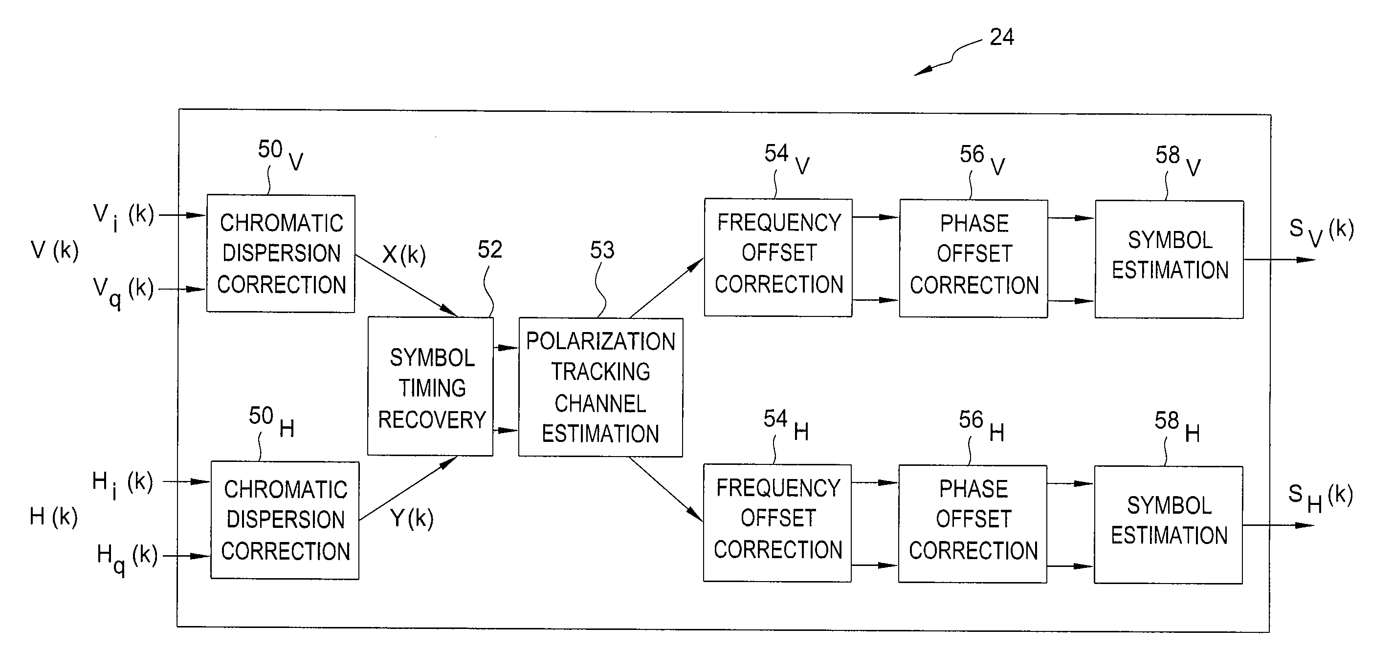
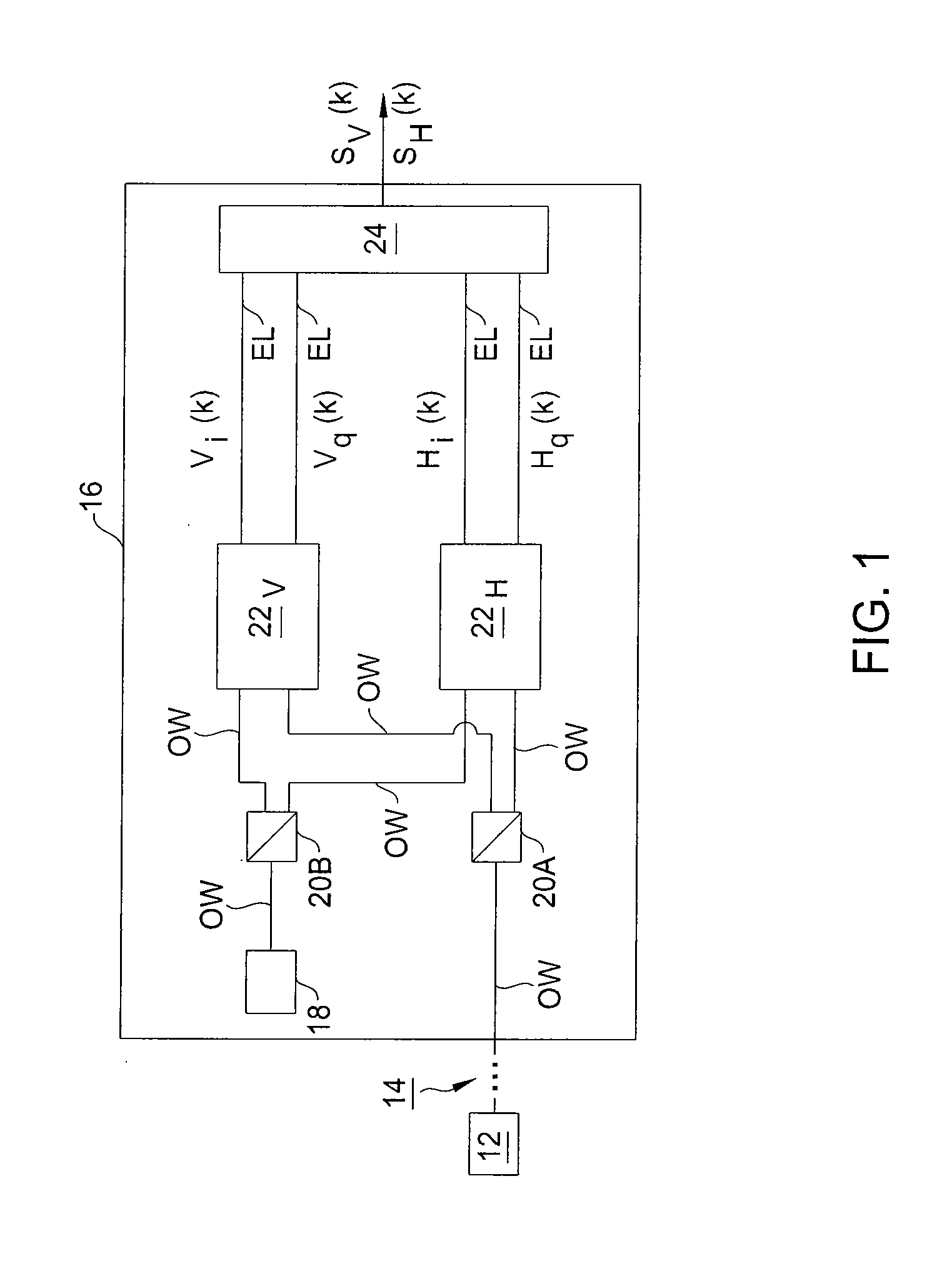
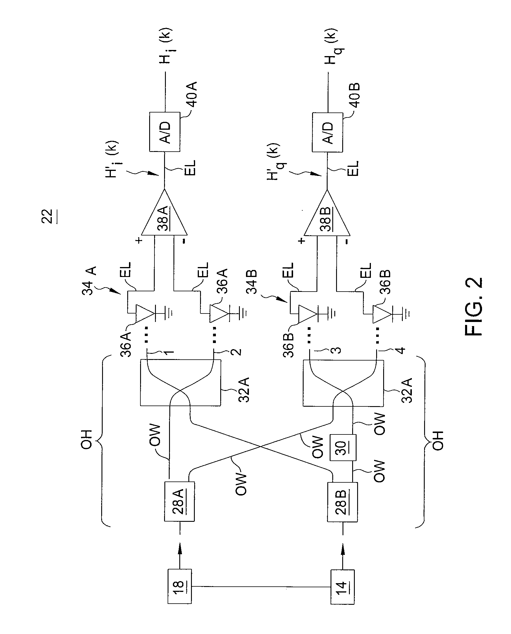
[0021]Embodiments will be primarily described within the context of a DSP processing block for a coherent optical receiver comprising one or more optical hybrids. However, those skilled in the art and informed by the teachings herein will realize that such embodiments are also applicable to any DSP-enhanced receiver implementing any known method or components for receiving a coherent signal.

[0022]Symbol timing recovery in PDM (polarization division multiplexing) optical coherent system needs to satisfy a few critical requirements. The first requirement is that symbol phase detection (timing error detection) needs fast polarization tracking capability or polarization transparency characteristics due to the rapid and arbitrary change in the state of polarization in fiber transmission system. The second is that phase detection and correction (interpolator) needs a very short or no feedback scheme due to the fast jitter and rapid change in optical polarization. The third requirement is ...


PUM


Abstract

A method, apparatus and system for providing clock and data recovery in a receiver for receiving a high speed coherent polarization division multiplexed optical signal using a digital signal processing block including a spectral domain spatial combiner are provided.

Description

FIELD OF THE INVENTION[0001]The invention relates to optical receivers and, more particularly, to clock recovery within a polarization division multiplexed (PDM) coherent optical receiver.BACKGROUND[0002]Clock and data recovery (CDR) in digital signal processing (DSP) based optical receivers is challenging if the received signal is distorted by chromatic dispersion, polarization mode dispersion or non-linear effects. Traditional digital clock recovery schemes are too complex to be implemented at data rates typically used in optical communications.[0003]Clock and data recovery in digital signal processing (DSP) based optical receivers can be performed either in analog domain, digital domain, or in a mixed-mode fashion.[0004]In an analog clock and data recovery scheme, the unprocessed signal before digitization is used for extracting a clock signal. This imposes limits on the maximum signal distortion (chromatic dispersion, polarization-mode dispersion, non-linearity) a receiver can h...

Claims


Application Information

Patent Timeline
Patent Type & Authority Applications(United States)
IPC IPC(8): H04J14/06
CPCH04B10/60H04L7/027H04L7/0029H04J14/06H04L7/0278
Inventor KANEDA, NORIAKILEVEN, ANDREAS B.WEISSER, STEFAN
Owner ALCATEL LUCENT SAS
Why Eureka
Try Eureka