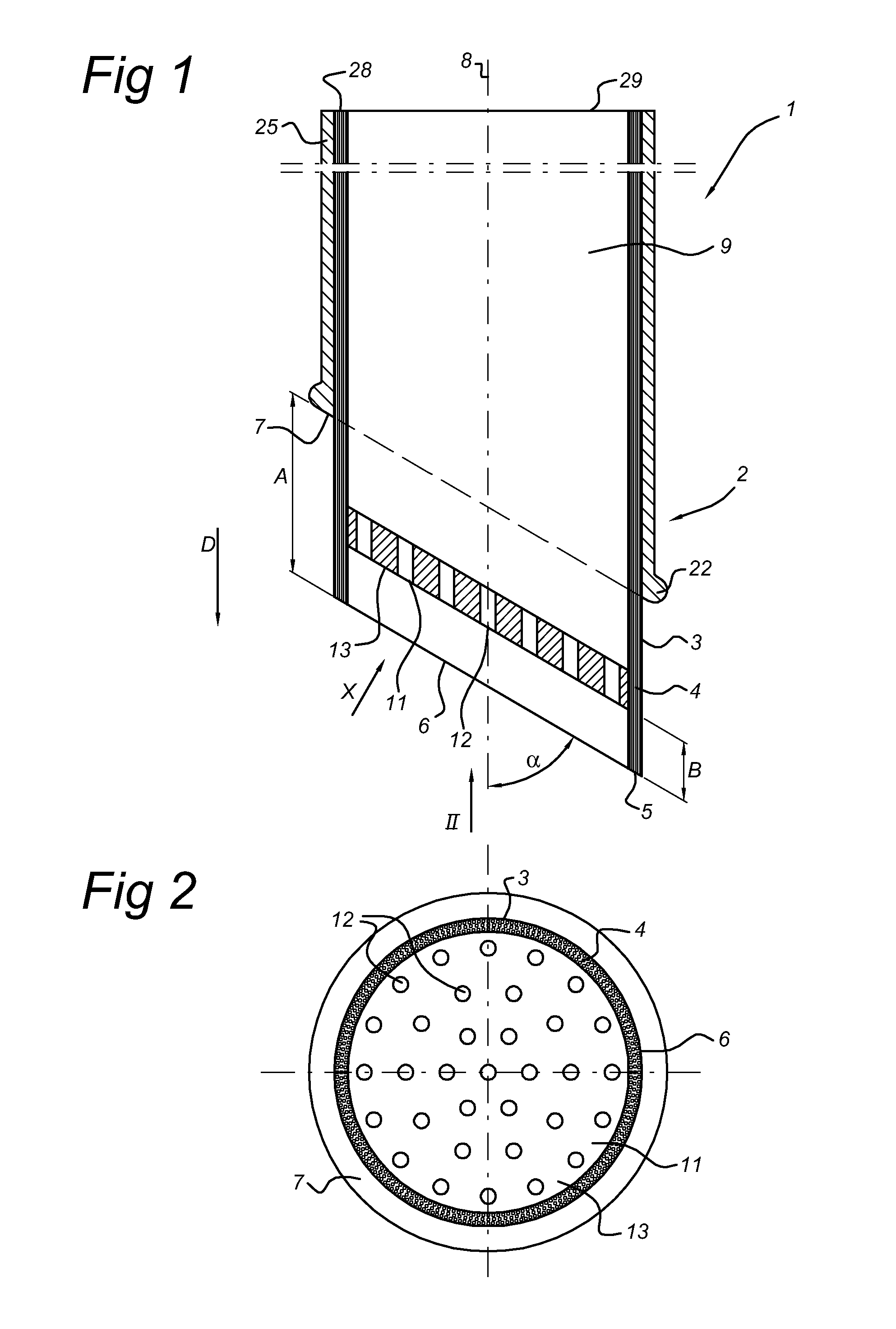
[0015]According to another further embodiment, the tubular arrangement of optical fibres has, viewed in a cross-section transverse to the longitudinal axis of the catheter, a circular cross section, wherein, viewed perpendicular to the light emergence surface, the shape of the light emergence surface is elliptical. This ensures that the aperture created in the wall of the
target vessel allows for a optimal flow characteristics of the blood flowing from the target vessel into the graft vessel or from the graft vessel into the target vessel.
[0016]According to still another further embodiment, the stop surface and light emergence surface are parallel to each other. The stop surface forms locally a radial bulge on the outer surface of the catheter. When the catheter is inserted into the graft vessel, this bulge will be visible as a bulge in the wall of the graft vessel or at least tangible with the fingers of the surgeon. Taking into account that the stop surface and light emergence surface are parallel to each other, this means that the surgeon can use the bulge as a reference for the orientation of the light emergence surface. This enables the surgeon to control or correct the orientation of the light emergence surface with respect to the wall of the target vessel.
[0017]In order to remove the flap of wall tissue left after burning away the ring of tissue, it is advantageous to provide the distal part of the catheter with a gripper for gripping tissue inside the tubular bundle of light beams. According to the invention, the gripper preferably comprises a hollow channel extending within the tubular arrangement of fibres and connectable to a vacuum source, wherein the distal end of the channel defines a suction mouth. In order to ensure a reliable
cutting through of the wall tissue of the target vessel by the
laser light beams as well as a firm gripping of the
cut out part of the wall tissue, it is according to the invention advantageous to arrange the suction mouth at a distance proximally from the light emergence surface and so that it defines a
suction surface parallel to the light emergence surface. The
suction surface parallel to the light emergence surface ensures an easy gripping of the
cut out part all over its surface.
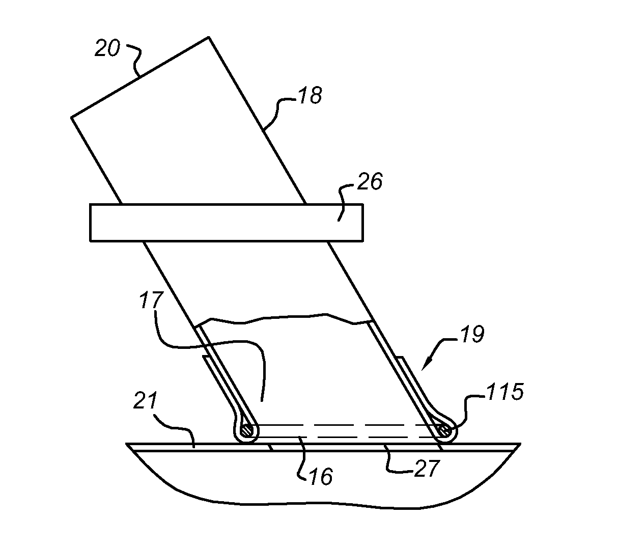
[0020]a ring member having dimensions adapted for, on the one hand,
insertion of the distal end of the tubular arrangement of optical fibres through said ring member and for, on the other hand, preventing passage of the stop surface through said ring member.
[0021]Before connecting the graft vessel to the target vessel, the graft vessel will be prepared for the bypass procedure by inserting one end of the graft vessel through the ring member and folding back the end of the graft vessel over the ring member. Before using the laser catheter, this folded end of the graft vessel, enclosing the ring member, will be attached to the wall of the target vessel. Subsequently, when the laser catheter has been introduced into the graft vessel and the laser operation is performed, the ring member will prevent the laser catheter from advancing too far into the target vessel as soon as the stop surface comes to rest onto the ring member.
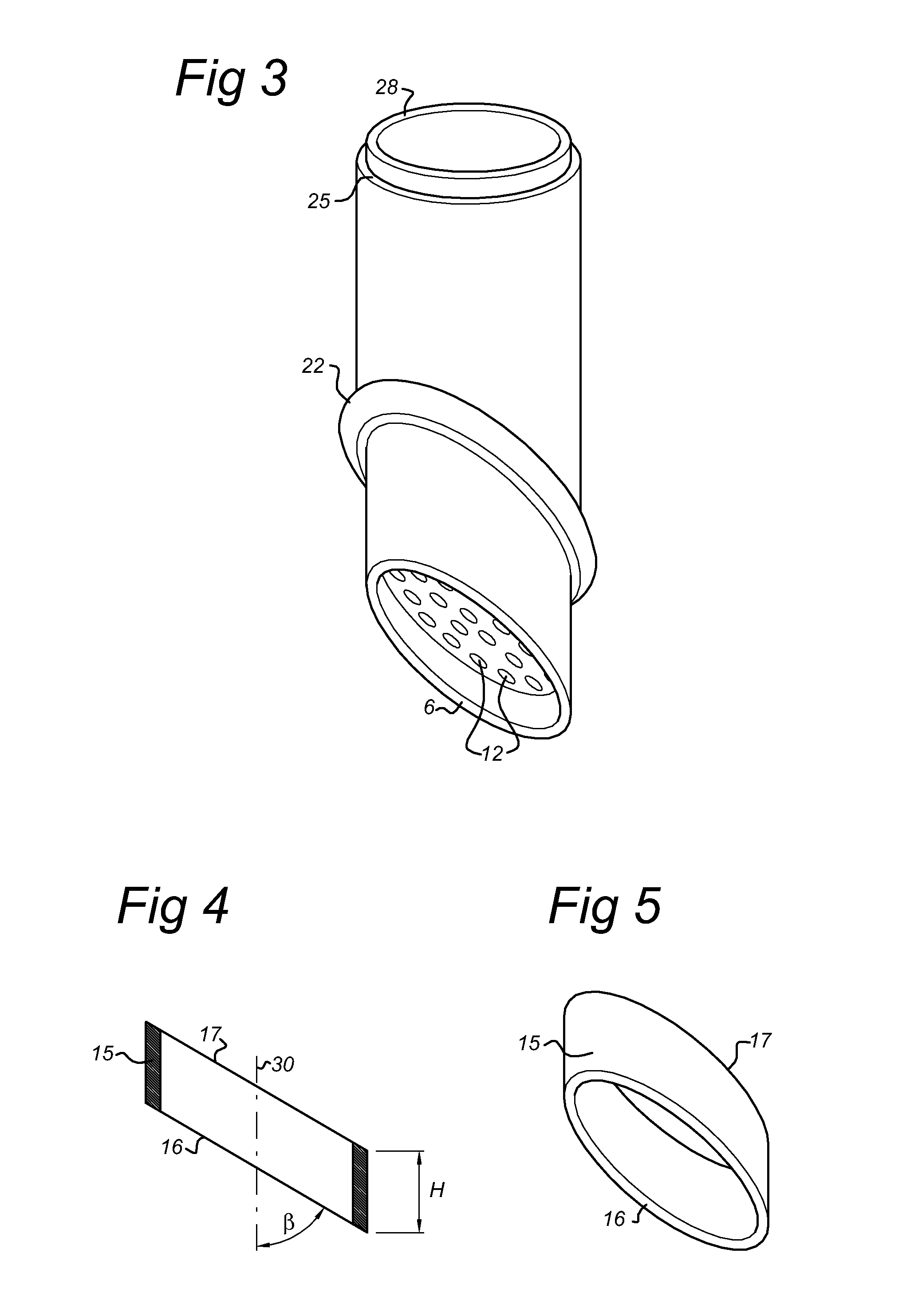
[0022]According to a further embodiment of the
assembly according to the invention it is advantageous when the ring member has an axial height which is at least 1 mm, such as in the range of [1, 5] mm or preferably in the range of [1, 3] mm, when the ring member has two opposing axial end faces, and when the angle between at least one of said axial end faces and the axial direction of the ring member corresponds to said slanting angle. A ring member having a axial height of at least 1 mm, such as 1 to 3 mm (including both 1 and 3 mm), provides a tubular guide for the distal ends of the optical fibres. This tubular guide helps preventing tilting of the laser catheter with respect to the target vessel during the laser procedure. The angle of the end face of the ring member, which faces the target vessel, being equal to the slanting angle, assists in ensuring that the light emergence surface is kept parallel to the wall of the target vessel during the laser operation. Preferably, both the axial end faces of the ring member are mutually parallel. This provides that the resting surface for the stop surface lies all around the ring member at the same distance from the target vessel.

