
Access and tissue modification systems and methods

a tissue modification and access technology, applied in the field of access and tissue modification systems and methods, can solve the problems of loss of control of the treatment device or implant, short hospital stay, and minimally-invasive techniques

Inactive Publication Date: 2010-12-30
BAXANO
View PDF99 Cites 431 Cited by
  • Summary
  • Abstract
  • Description
  • Claims
  • Application Information

AI Technical Summary

Benefits of technology

[0035]In many embodiments, the surface will be shifted by applying torque to the rigid portion from outside the body portion. The rigid portion can then rotate the flexible portion about the axis so as to shift an orientation of the first surface toward a target region of the target tissue. Where the target tissue has a convex surface defining an outward orientation and an inward orientation, and where the first surface is bordered by first and second opposed edges, the target tissue adjacent the first edge may be inward of the target tissue adjacent the second edge. As a result, the tension of the flexible portion may induce rolling of the flexible portion about the axis toward the first edge. The torquing of the shaft portion may counteract the tension-induced rolling to inhibit flipping of the flexible portion.
[0309]Also described herein are devices and methods for implanting and anchoring an electrical lead. An electrical lead may be used to help treat chronic pain. The devices and methods described herein may allow precise implantation and anchoring of a lead. Adequate anchoring of implants (such as leads) is critical to prevent migration and eventual failure of these devices.

Problems solved by technology

This may result in shorter hospital stays, or allow outpatient treatment.
Unfortunately, the use of minimally-invasive techniques has often required a loss in control of the treatment device or implant, as the treatment sites are often deep within the body, proving both difficult to access, as well as difficult to manipulate the device when the body region is minimally invasively accessed.
In particular, finding leverage to position or manipulate minimally invasive devices once deployed has proven extremely difficult.
As a result, complex and expensive tools have been created to allow manipulation of distally-positioned devices or implants within the body.
Even in variations of minimally invasive procedures in which a second access port is used, coordination of the two access ports at the target has proven difficult, particularly when one or more devices are inserted through different access ports and required to meet at an internal site.
Finally, manipulation of implants and devices using any of these minimally invasive techniques has also proven difficult.
For example, when treating small or enclosed body regions such as joints, or regions surrounded by sensitive non-target tissue, manipulation of a device or implant within this space has been limited by the ability to control the distal end of the device from a proximal position.
This may lead to undesirable and dangerous kinking, bending, and torqueing of the access device and / or implant.

Method used


Image

  • Access and tissue modification systems and methods
  • Access and tissue modification systems and methods
  • Access and tissue modification systems and methods

Examples


example 1

Neural Localization when Treating Spinal Stenosis

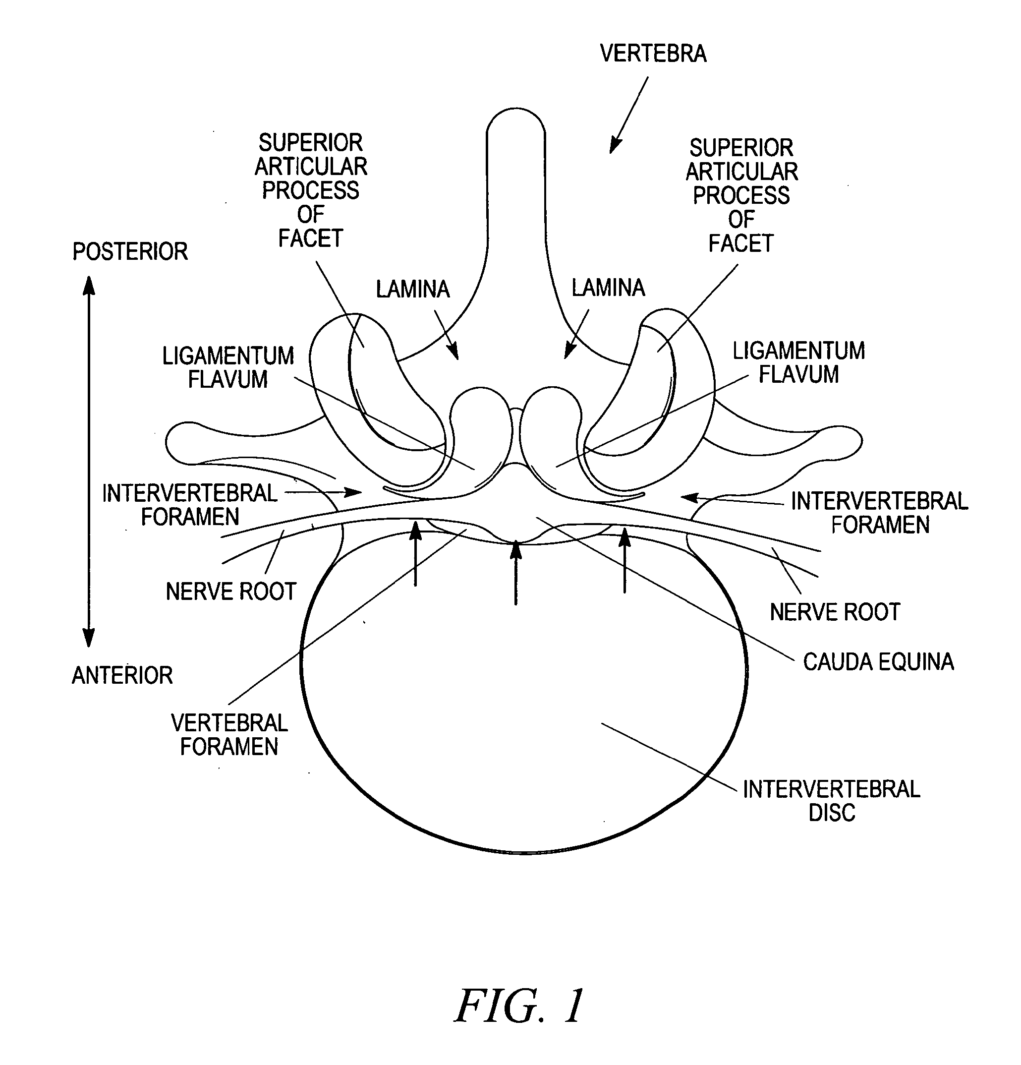
[1445]One area of surgery which could benefit from the development of less invasive techniques including neural localization is the treatment of spinal stenosis. Spinal stenosis often occurs when nerve tissue and / or blood vessels supplying nerve tissue in the lower (or “lumbar”) spine become impinged by one or more structures pressing against them, causing pain, numbness and / or loss of function in the lower back and / or lower limb(s). In many cases, tissues such as ligamentum flavum, hypertrophied facet joint and bulging intervertebral disc impinge a nerve root as it passes from the cauda equine (the bundle of nerves that extends from the base of the spinal cord) through an intervertebral foramen (one of the side-facing channels between adjacent vertebrae). Here we provide one example of a device for determining if a nerve is nearby that may be used as part of method for treating spinal stenosis.

[1446]FIG. 329 is a top view of a verteb...


PUM


Abstract

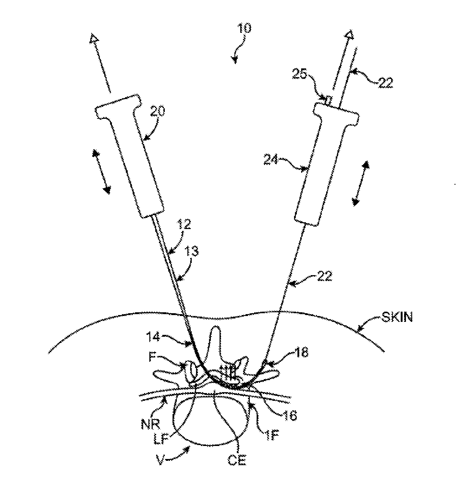
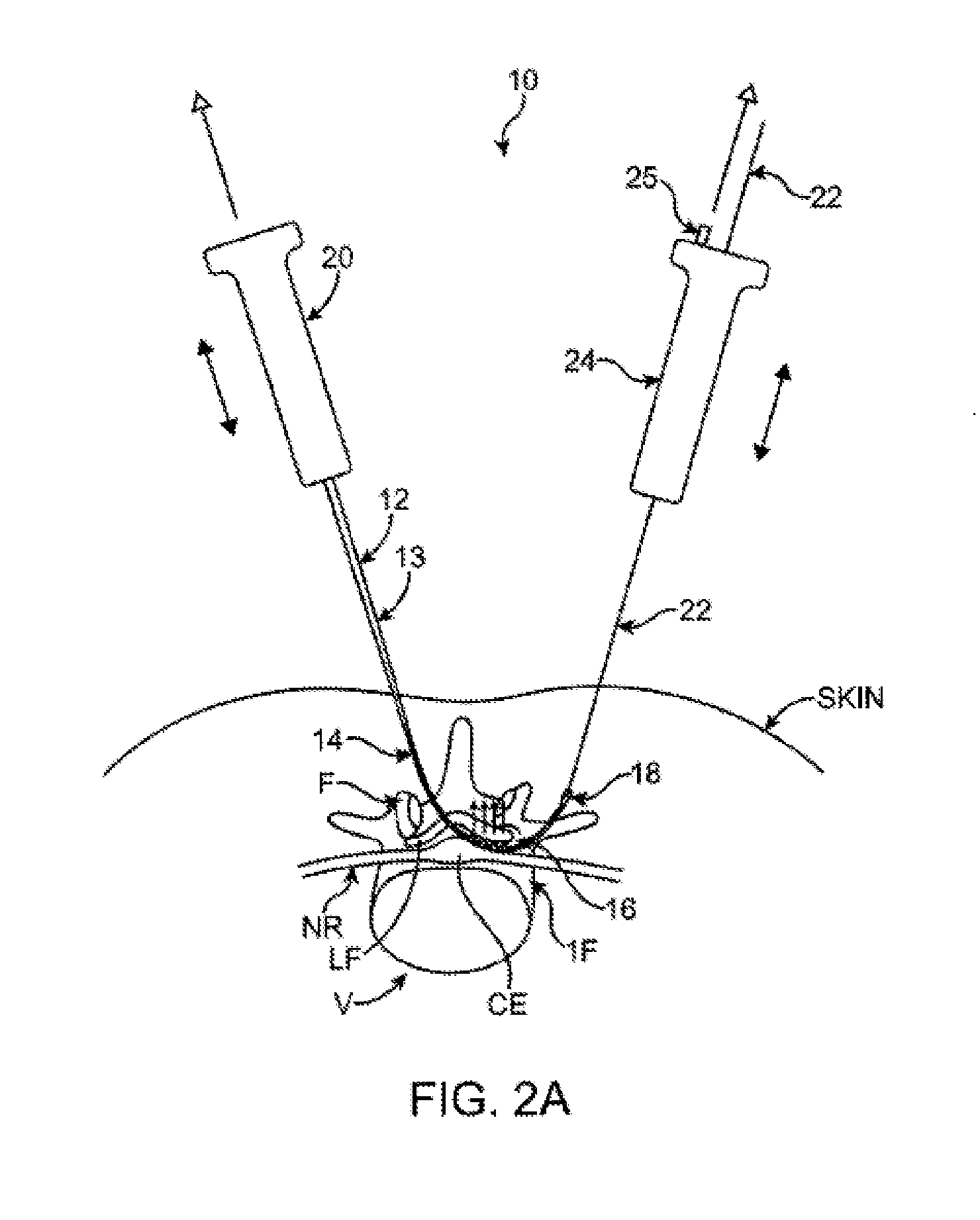
Described herein are methods and systems for precisely placing and / or manipulating devices within the body by first positioning a guidewire or pullwire through the body from a first location, around a curved pathway, and out of the body through a second location, so that the distal and proximal ends of the guidewire extend from the body, then pulling a device into position using the guidewire. The device to be positioned within the body is coupled to the proximal end of the guidewire, and the device is pulled into the body by pulling on the distal end of the guidewire that extends from the body. The device may be bimanually manipulated by pulling the guidewire distally, and an attachment to the device that extends proximally, allowing control of both the proximal and the distal ends. In this manner devices (and particularly implants such as innerspinous distracters, stimulating leads, and disc slings) may be positioned and / or manipulated within the body. Devices to modify tissue may also be positioned or manipulated so that a target tissue within the body is modified.

Description

CROSS REFERENCE TO RELATED APPLICATIONS[0001]This application is a continuation-in-part to U.S. patent application Ser. No. 11 / 952,934, titled “TISSUE REMOVAL DEVICES AND METHODS”, filed on Dec. 7, 2007; which claims the benefit of U.S. Provisional Patent Application No. 60 / 869,070, titled “FLEXIBLE TISSUE REMOVAL DEVICES AND METHODS”, filed on Dec. 7, 2006.[0002]This application is a also a continuation-in-part to U.S. patent application Ser. No. 12 / 637,447, titled “DEVICES AND METHODS FOR TISSUE MODIFICATION”, filed Dec. 14, 2009; which is a continuation of U.S. patent application Ser. No. 12 / 428,369, titled “DEVICES AND METHODS FOR TISSUE MODIFICATION”, filed on Apr. 22, 2009; which is a continuation of U.S. patent application Ser. No. 11 / 251,165, titled “DEVICES AND METHODS FOR TISSUE MODIFICATION”, filed on Oct. 15, 2005, now U.S. Pat. No. 7,555,307; which claims the benefit of U.S. Provisional Application No. 60 / 619,306, titled “METHODS AND APPARATUS FOR THE TREATMENT OF TISSU...

Claims


Application Information

Patent Timeline
Patent Type & Authority Applications(United States)
IPC IPC(8): A61B17/70A61B17/88
CPCA61B5/0488A61B5/1076A61B5/1101A61B10/0275A61B10/0283A61B17/0218A61B17/06109A61B17/14A61B17/1604A61B17/1611A61B17/1626A61B17/1635A61B17/1659A61B17/1671A61B17/1757A61B17/320016A61B17/32002A61B17/3207A61B17/320783A61B17/3401A61B17/3403A61B17/3468A61B17/3496A61B17/683A61B17/7065A61B17/7068A61B17/7092A61B17/842A61B17/8897A61B18/14A61B19/54A61B2017/00039A61B2017/00261A61B2017/00469A61B2017/00557A61B2017/00986A61B2017/0225A61B2017/143A61B2017/145A61B2017/320004A61B2017/320008A61B2017/32006A61B2019/4027A61B2019/461A61B2019/464A61B2019/481A61B2019/5248A61F2/0063A61B17/29A61B17/32053A61B17/320708A61B17/320758A61B17/3421A61B18/1477A61B18/1487A61B19/40A61M25/09041A61M25/0905A61N1/0551A61N1/08A61B2017/00287A61B2017/003A61B2017/00349A61B2017/00477A61B2017/00867A61B2017/320044A61B2018/1407A61B2018/1425A61N2001/0578A61B17/320068A61B5/7207A61B18/02A61B18/20A61B2018/0044A61B2018/00565A61B2018/00577A61B2018/00595A61B2018/00601A61B2018/1412A61B2018/1465A61F2/4611A61B5/407A61B90/04A61B2090/0427A61B2034/2048A61B2090/064A61B2090/061A61B2090/08021A61B90/39A61B17/149A61B2017/32007A61B2017/320069A61B5/389A61B5/395
Inventor SCHMITZ, GREGORY P.WALLACE, MICHAEL P.CHUNG, WINNIEBORGSTROM, AMIE R.BLEICH, JEFFERY L.ARCENIO, GREGORY B.LEGUIDLEGUILD, RONALDLEGUIDLEGUILD, ROY
Owner BAXANO
Learn More